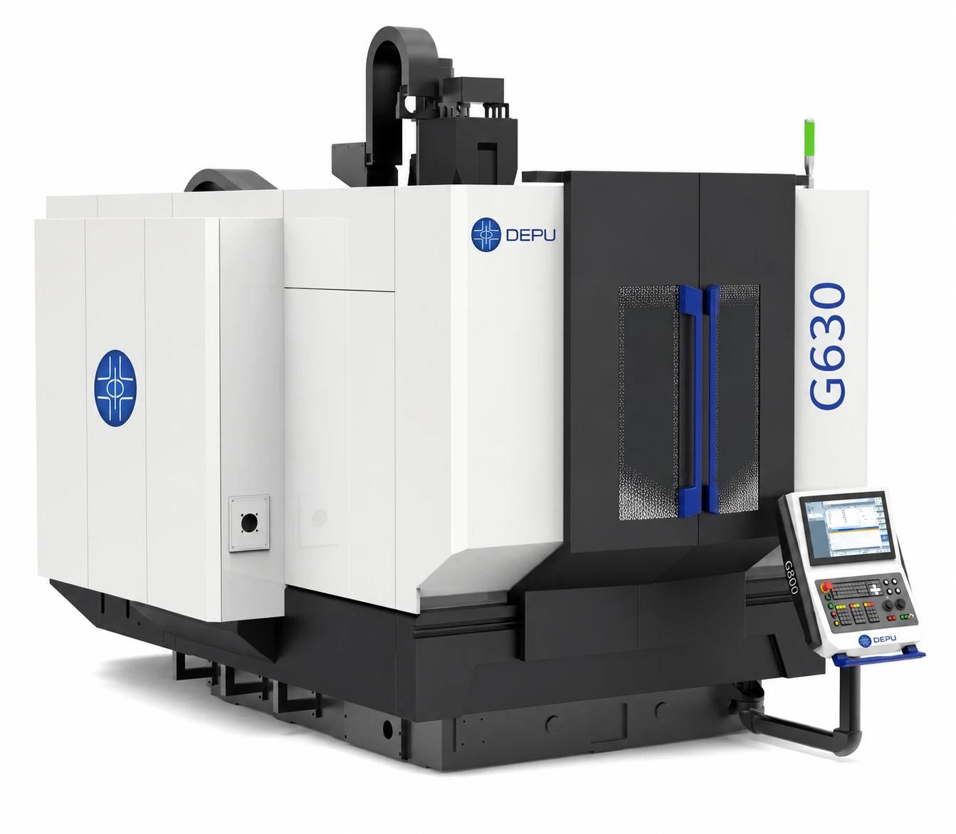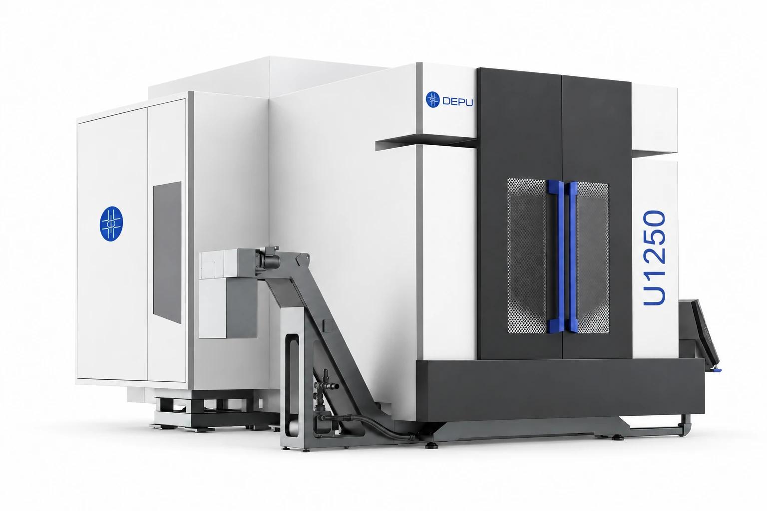
However, not every 5-axis CNC machine uses the same rotary-axis combination or moves the workpiece and cutting tool in the same way. Understanding how the five axes work together helps you evaluate machine configurations and choose equipment that fits your manufacturing requirements.
What Are the 5 Axes on a CNC Machine?
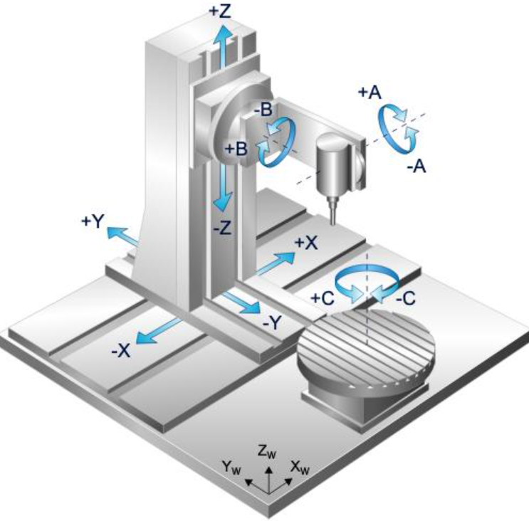
A typical 5-axis CNC machining center combines three linear movements with two rotary movements.
The three linear axes are X, Y, and Z. The three standard rotary-axis designations are A, B, and C. A particular five-axis machine uses two of those three rotary axes.
| Axis | Movement type | Definition |
|---|---|---|
| X-axis | Linear | Movement along the X direction |
| Y-axis | Linear | Movement along the Y direction |
| Z-axis | Linear | Movement along the Z direction |
| A-axis | Rotary | Rotation around the X-axis |
| B-axis | Rotary | Rotation around the Y-axis |
| C-axis | Rotary | Rotation around the Z-axis |
Swipe to compare →
For example, a machine may use an XYZAC or XYZBC configuration. Both are five-axis arrangements because each combines three linear axes with two rotary axes.
The axis names follow standard machine-tool coordinate conventions. The actual physical movement depends on the machine’s mechanical design: the worktable, spindle head, or another machine component may move to produce the required relative motion between the cutting tool and workpiece.
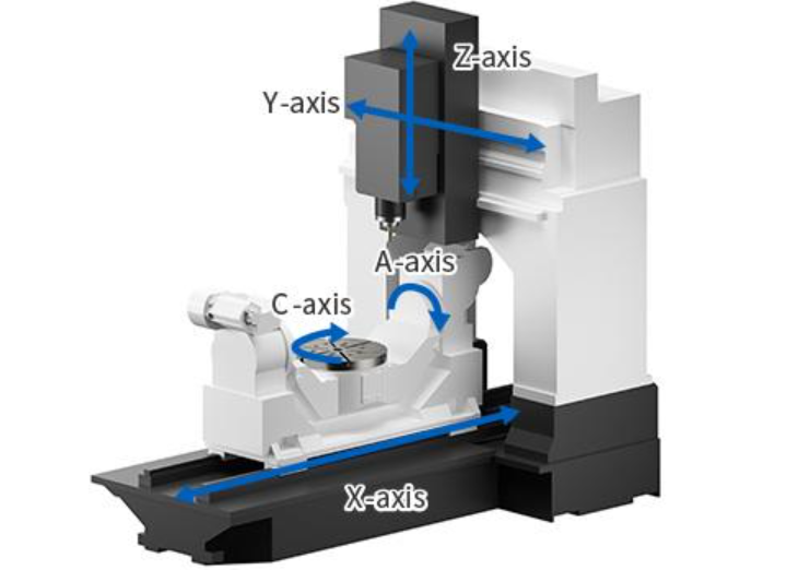
X-Axis: Left-to-Right Linear Movement
The X-axis controls linear movement along the machine’s X direction.
On many vertical machining centers, you can think of this as left-to-right movement when viewing the machine from the front. The X-axis helps position the cutting tool across the length of the workpiece.
For example, when machining a long aluminum housing, X-axis movement allows the tool to travel along the part to mill pockets, slots, holes, and other features.
The exact component that moves depends on the machine design. Some machines move the worktable along X, while others move the spindle assembly.
Y-Axis: Front-to-Back Linear Movement
The Y-axis controls linear movement along the direction perpendicular to the X-axis.
On a typical vertical machining center, this is often described as front-to-back movement. Together, the X- and Y-axes position the cutting tool across the horizontal machining plane.
These movements are essential for machining features distributed across a workpiece, including pockets, contours, and drilled holes.
Z-Axis: Movement Along the Spindle Direction
The Z-axis controls linear movement along the machine’s primary tool-axis direction.
On a typical vertical milling machine, the spindle is vertical, so Z-axis movement is commonly described as up and down. It determines the cutting tool’s position relative to the workpiece surface and controls cutting depth during operations such as drilling, facing, and pocketing.
Keep in mind that Z does not always mean vertical in the physical sense. On a horizontal machining center, the Z-axis follows the machine’s principal spindle direction, which is horizontal.
A-Axis: Rotation Around the X-Axis
The A-axis is a rotary axis that rotates around the X-axis.
This movement changes the angular orientation of the cutting tool or workpiece relative to the other axes. It allows the machine to approach surfaces and features from different angles.
On a trunnion-style machining center, an A-axis commonly provides the tilting movement of the cradle or rotary table.
For example, if you need to machine an angled surface on a metal component, A-axis movement can position the workpiece so the cutting tool can reach that surface from a suitable direction.
B-Axis: Rotation Around the Y-Axis
The B-axis rotates around the Y-axis.
Like the A-axis, it provides angular movement, but around a different coordinate direction. Depending on the machine configuration, B-axis movement may tilt the worktable or swivel the spindle head.
This movement can help you machine inclined surfaces, angled holes, and complex geometries that are difficult to reach with three linear axes alone.
C-Axis: Rotation Around the Z-Axis
The C-axis rotates around the Z-axis.
It provides rotation around the Z direction and can be used to position a workpiece at different angular orientations or support continuous rotary movement during machining.
For example, when a component has features distributed around its circumference, C-axis rotation can bring different areas into the required machining position.
A five-axis machining center may combine C-axis movement with either an A-axis or a B-axis.
Remember: A, B, and C are the three standard rotary-axis designations, but a typical five-axis machining center uses only two of them alongside X, Y, and Z. You should check the machine’s actual kinematic configuration rather than assuming every machine uses XYZAB.
How Do the Five Axes Work Together?
The purpose of five-axis machining is to control both the position and orientation of the cutting tool relative to the workpiece.
In three-axis machining, the machine moves along X, Y, and Z. The tool can reach different positions, but its orientation relative to the workpiece remains fixed during a typical operation. To machine another face or an angled feature, you may need to reposition the workpiece or use additional equipment.
Five-axis machining adds two rotary movements. These allow the machine to change the relative angle between the tool and workpiece while coordinating the three linear axes.
This additional movement is useful when your parts include:
-
Angled holes and inclined surfaces
-
Curved or sculpted surfaces
-
Multiple machined faces
-
Deep cavities and difficult-to-reach features
-
Blades, impellers, and other complex geometries
Consider an aerospace component with several angled surfaces. On a three-axis machine, you may need multiple setups to reach all the required features. A five-axis machine can often access more of those surfaces in a single setup.
Fewer setups can reduce repositioning errors, simplify workholding, and improve process consistency. The actual benefits depend on the part geometry, machine configuration, tooling, programming, and machining process.
Does Every 5-Axis CNC Machine Use the Same Axes?
No. Five-axis CNC machines use different combinations of rotary axes depending on their mechanical design.
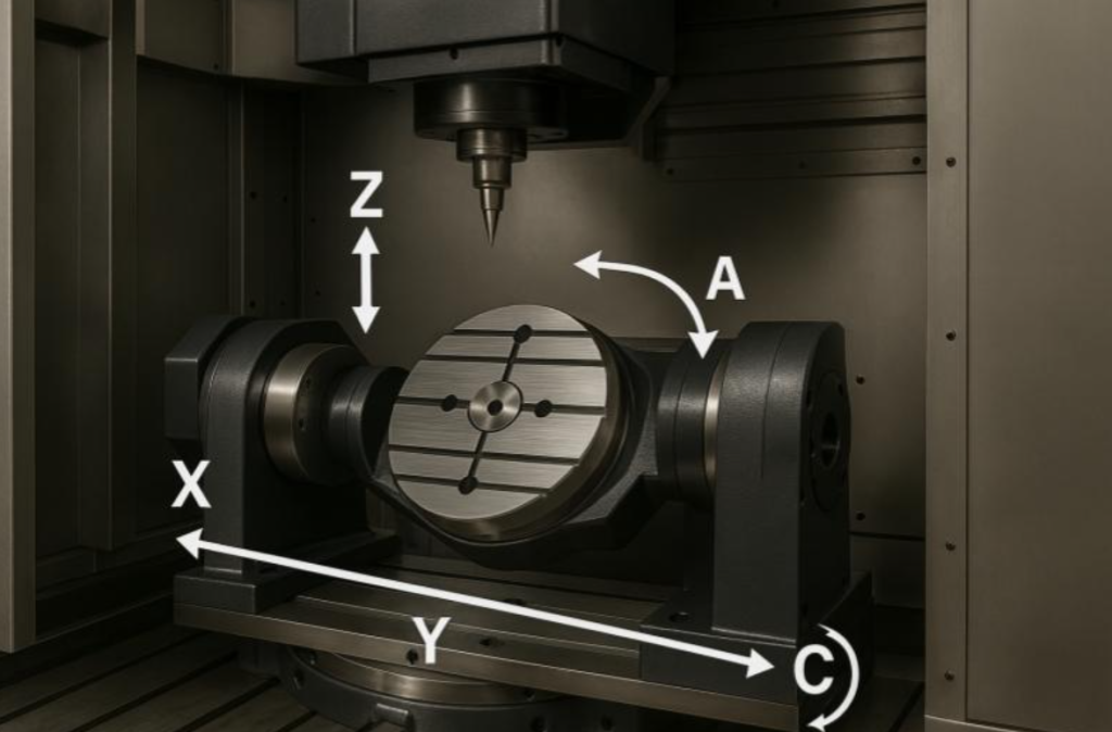
Common configurations include:
| Configuration | Linear axes | Rotary axes |
|---|---|---|
| XYZAC | X, Y, Z | A and C |
| XYZBC | X, Y, Z | B and C |
| XYZAB | X, Y, Z | A and B |
Swipe to compare →
A trunnion-table machine, for example, may use an A-axis to tilt the workpiece and a C-axis to rotate it. A swivel-head machine may use two rotary axes in the spindle head instead.
The axis combination tells you which coordinate directions are involved in the machine’s rotary movements. It does not, by itself, tell you whether the workpiece or the cutting tool moves.
When comparing machines, look beyond the axis names. You should also check:
-
Rotary-axis travel range
-
Maximum rotary speed
-
Rotary-axis torque and load capacity
-
Positioning accuracy and repeatability
-
Workpiece clearance throughout the rotary range
-
Whether the machine supports simultaneous five-axis machining
These details have a direct impact on which parts you can machine and how efficiently you can produce them.
Trunnion Table vs. Swivel Head: How Are the Rotary Axes Designed?
One of the most important differences between five-axis CNC machines is where the rotary movements take place.
Two common designs are trunnion-table machines and swivel-head machines.
Trunnion or Cradle Table Design
A trunnion-style machine uses a tilting rotary table to change the workpiece’s orientation. The workpiece is mounted on the table, which rotates around two rotary axes.
This design is commonly used for compact and medium-sized components that fit within the table’s working envelope and load capacity.
Advantages:
-
Provides access to multiple sides of a workpiece.
-
Can reduce the need for repeated manual repositioning.
-
Supports 3+2 and, on appropriately configured machines, simultaneous five-axis machining.
-
Can be suitable for precision components, molds, and complex metal parts.
Limitations:
-
The workpiece must fit within the rotary table’s dimensions and load rating.
-
Large parts may encounter clearance limitations as the table tilts.
-
Heavy workpieces place greater demands on the rotary structure and workholding system.
When evaluating a trunnion machine, check the maximum workpiece diameter, height, weight, rotary travel, and clearance at different table angles.
Swivel-Head Design
A swivel-head machine changes the spindle head’s orientation instead of relying on a tilting worktable.
The workpiece remains on a fixed table while the spindle head moves to reach different machining angles.
This architecture can be useful when you need to machine large or heavy components that are difficult to rotate.
Advantages:
-
The workpiece remains on a fixed table.
-
Can accommodate large or heavy components, depending on machine capacity.
-
Provides different tool orientations for machining complex surfaces.
-
Can be suitable for large industrial components and structural parts.
Limitations:
-
The spindle head has its own angular travel and clearance limits.
-
Tool reach and machine geometry affect access to certain features.
-
Structural rigidity and spindle capability remain critical for demanding metal-cutting operations.
Which Design Should You Choose?
Neither design is automatically better. Your workpiece dimensions, weight, geometry, and machining requirements should guide the decision.
If you mainly machine smaller or medium-sized complex components, a trunnion-style machine may be a practical choice. If your production involves large, heavy workpieces, a swivel-head configuration may deserve closer evaluation.
Ask the manufacturer to review a representative part drawing or 3D model. This helps establish whether the machine can reach the required surfaces without collisions or unnecessary repositioning.
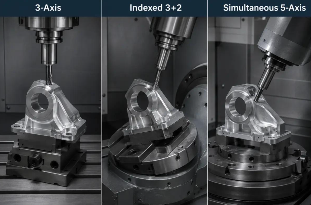
What Is the Difference Between 3+2 and Simultaneous 5-Axis Machining?
Both methods use a five-axis CNC machine, but they use the rotary axes differently.
3+2 Indexed Machining
In 3+2 machining, the machine first uses its two rotary axes to position the workpiece or tool at a selected angle.
Once the required orientation is reached, the rotary axes remain stationary while the machine performs the cutting operation using the three linear axes.
This is why the process is also called indexed five-axis machining.
3+2 machining is useful when:
-
You need to machine several faces of a part.
-
Features can be machined from fixed tool orientations.
-
You want to reduce manual repositioning.
-
Your process does not require continuous changes in tool orientation.
For many prismatic components with angled faces or holes, 3+2 machining can be an efficient approach.
Simultaneous 5-Axis Machining
In simultaneous five-axis machining, the three linear axes and two rotary axes coordinate their movements during the cutting process.
This allows the machine to continuously adjust the tool’s position and orientation as it follows a complex toolpath.
Simultaneous five-axis machining is useful when:
-
You need to machine complex freeform surfaces.
-
The tool must continuously change its orientation.
-
Your part includes blades, impellers, or sculpted geometries.
-
You need to maintain a suitable tool approach angle along a complex surface.
Simultaneous machining generally requires more advanced CAM programming, appropriate machine kinematics, and careful collision checking.
The distinction is straightforward: 3+2 machining uses the rotary axes to position the tool or workpiece before cutting, while simultaneous five-axis machining coordinates all five axes during cutting.
What Can a 5-Axis CNC Machine Make?
Five-axis machining is useful across industries that manufacture complex, high-value components. A machine’s actual suitability depends on its work envelope, spindle, rigidity, tooling, and material-cutting capabilities.
Aerospace Components
Aerospace parts often include complex surfaces, angled features, thin walls, and demanding dimensional requirements.
Five-axis machining can help you manufacture:
-
Turbine and compressor components
-
Impellers and blades
-
Structural brackets
-
Complex housings
-
Aerospace structural components
The ability to reach multiple surfaces with fewer setups can be particularly valuable when machining complex aerospace geometries.
Medical Components
Medical manufacturing includes parts with complex contours and demanding dimensional requirements.
Potential applications include:
-
Orthopedic components
-
Surgical instrument parts
-
Implant components
-
Precision medical equipment components
Material compatibility, surface finish, process validation, and inspection requirements are especially important in medical manufacturing. A five-axis machine is only one part of a qualified production process.
Automotive Components
Five-axis CNC machining can support the production of complex automotive components, prototypes, and precision tooling.
Examples include:
-
Engine and transmission components
-
Complex housings
-
Precision molds
-
Prototypes and specialized components
For production environments, you should also evaluate cycle time, automation options, tool life, and the repeatability of the complete machining process.
Molds, Dies, and Precision Components
Mold and die manufacturing often involves curved surfaces, deep cavities, angled walls, and complex geometries.
Five-axis machining can help you reach these features from different tool orientations. Depending on the part, this may reduce the need for multiple setups and help improve surface continuity.
Typical applications include injection molds, die-casting molds, precision dies, and complex tooling.
How Do You Choose the Right 5-Axis CNC Machine?
Understanding the five axes is only the first step. If you’re purchasing a machine for your factory, you also need to match its configuration to your actual production requirements.
Use these steps to narrow down your options.
Step 1: Define Your Workpiece Dimensions and Weight
Start with your largest and heaviest parts.
Record:
-
Maximum workpiece length, width, and height
-
Maximum workpiece weight
-
Required machining angles
-
Fixture dimensions
-
Clearance requirements
Do not rely only on the machine’s advertised table diameter. A part that fits on the table may still interfere with the machine structure when the rotary axes move.
Step 2: Choose the Right Machine Architecture
Decide whether a trunnion-table, swivel-head, or hybrid configuration is more appropriate.
A trunnion machine may suit components that fit within the rotary table’s capacity. A swivel-head machine may be worth considering when the workpiece is too large or heavy to rotate conveniently.
Ask the manufacturer to confirm the machine’s actual kinematics and available rotary-axis travel.
Step 3: Match the Spindle to Your Materials
The spindle must match your cutting requirements.
Consider:
-
Maximum spindle speed
-
Continuous and short-term spindle power
-
Torque across the operating speed range
-
Tool interface
-
Cooling system
-
Toolholder and cutter compatibility
For example, aluminum machining may benefit from higher spindle speeds, while demanding steel operations may require a different balance of torque, power, and rigidity.
Do not select a spindle based on maximum RPM alone.
Step 4: Check CNC Control and CAM Compatibility
Your CNC control and CAM software must work together to generate and execute the required five-axis toolpaths.
Confirm that the machine supports:
-
Your required 3+2 or simultaneous five-axis operations
-
RTCP or an equivalent tool-center-point function
-
Suitable machine kinematic definitions
-
Compatible postprocessors
-
Tool and workpiece measurement options
-
Collision detection and simulation workflows
A compatible postprocessor is particularly important. Incorrect machine kinematics or rotary-axis definitions can cause positioning errors and potential collisions.
Step 5: Evaluate Accuracy and Technical Support
Ask for the machine’s positioning accuracy and repeatability specifications, including the measurement conditions and relevant standards.
For demanding applications, also review:
-
Rotary-axis positioning accuracy
-
Thermal compensation capabilities
-
Machine calibration procedures
-
Spindle thermal stability
-
Service and maintenance arrangements
-
Operator training and technical support
If you’re purchasing from an overseas manufacturer, clarify installation, commissioning, warranty coverage, spare-parts availability, and service response before placing your order.
Step 6: Request a Machining Evaluation
Before making a final decision, provide the manufacturer with a representative part drawing or 3D model.
Ask the manufacturer to evaluate:
-
Whether the part fits within the machine’s working envelope.
-
Whether the rotary axes can reach the required orientations.
-
Whether any features create tool or fixture interference.
-
Which spindle and tool configuration is appropriate.
-
Whether 3+2 or simultaneous five-axis machining is required.
-
How the finished part will be inspected.
A machining demonstration or sample-part evaluation based on your own application can provide more useful information than comparing general machine specifications alone.
Why Consider DEPU for 5-Axis CNC Machining?
If you’re comparing five-axis CNC machine manufacturers, DEPU is one option to evaluate for industrial metalworking applications.
DEPU focuses on the research, development, and manufacturing of five-axis CNC machine tools and core components. According to company-provided information, its R&D work involves engineers from Germany and Taiwan, and many of its R&D engineers have more than 20 years of experience.
The company also reports approximately 3,800 active customers in Europe and cooperation with research and academic organizations, including the Southern Industrial Technology Research Institute, Chongqing University’s School of Mechanical Engineering, and the Southern Institute of Space Technology.
DEPU identifies ISO and CE certifications, High-Tech Enterprise certification, utility model patents, and design patents among its company credentials.
These details provide background about the manufacturer, but they should not replace a technical evaluation of the specific machine you plan to purchase. Before making a decision, review the exact model specifications, machine configuration, certification documents, application suitability, and service arrangements.
You can explore DEPU’s 5-axis CNC machining centers to compare available machine configurations.
Final Thoughts
The five axes on a CNC machine are three linear movements—X, Y, and Z—and two rotary movements selected from A, B, and C. Together, they let you control both the position and orientation of the cutting tool relative to the workpiece.
But understanding the axis names is only the beginning. The rotary-axis configuration, machine architecture, spindle capability, workpiece capacity, and CNC control all influence what a five-axis machine can do.
If you’re choosing a machine for your factory, start with your actual parts and machining requirements. Then compare trunnion-table and swivel-head designs, verify the machine’s working envelope, and request an application-specific machining evaluation. This approach will help you select a five-axis CNC machine that fits your production needs rather than relying on the axis count alone.
FAQ
1. What are the five axes of a CNC machine?
The five axes consist of three linear axes—X, Y, and Z—and two rotary axes selected from A, B, and C. The X, Y, and Z axes control linear movement. A rotates around X, B rotates around Y, and C rotates around Z.
2. What is the difference between A-axis, B-axis, and C-axis?
The difference is the direction of rotation:
-
A-axis rotates around the X-axis.
-
B-axis rotates around the Y-axis.
-
C-axis rotates around the Z-axis.
A typical five-axis CNC machine uses two of these rotary axes, depending on its mechanical configuration.
3. Does every five-axis CNC machine use A and B axes?
No. A five-axis machine uses X, Y, and Z plus two rotary axes. Common combinations include A and C, B and C, or A and B. The specific combination depends on the machine’s design.
4. Can all five axes move at the same time?
Yes. A machine configured for simultaneous five-axis machining can coordinate all five axes during a cutting operation. However, not every five-axis operation requires simultaneous movement. In 3+2 machining, the rotary axes position the tool or workpiece first, and the three linear axes perform the cutting while the rotary axes remain stationary.
5. Is a five-axis CNC machine better than a three-axis machine?
Not for every application. A three-axis machine may be more economical and entirely sufficient for parts with relatively simple geometries. A five-axis machine is more useful when your parts require multiple machining angles, complex surfaces, or access to several sides with fewer setups.
Your production volume, part geometry, tolerances, and budget should determine which machine is the better investment.
6. Can a five-axis CNC machine machine titanium and stainless steel?
Yes, provided the machine is properly configured for the material and cutting process. You need to consider spindle torque, machine rigidity, tooling, coolant delivery, workholding, and cutting parameters. The number of axes alone does not determine whether a machine can handle a particular metal.
7. What is the difference between a trunnion and a swivel-head five-axis machine?
A trunnion machine uses a rotary table to change the workpiece’s orientation. A swivel-head machine changes the spindle head’s orientation while the workpiece remains on a fixed table.
Trunnion machines are often suitable for smaller or medium-sized parts within their table capacity. Swivel-head machines can be advantageous for certain large or heavy workpieces. The right choice depends on the actual machine design and application.
Originally published by DEPU on 16 Nov 2026.