Why Dimensional Accuracy Is Non-Negotiable for Precision CNC Parts
GD&T as the Language of Functionality: Translating Design Intent to Real-World Performance
GD&T, or Geometric Dimensioning and Tolerancing, acts as the common language engineers use to communicate how parts should actually work when manufactured through precision CNC processes. Regular dimensional measurements only tell part of the story. With GD&T symbols, we're not just talking about sizes anymore but how components need to fit together, move relative to each other, and maintain proper interaction throughout their lifecycle. Take flatness specifications for example they stop those annoying wobbles in mounting plates. Perpendicularity requirements keep things square where they need to be. And position tolerances? They ensure those hole patterns line up perfectly with what they connect to. When done right, these controls save manufacturers from serious headaches down the road. Think about it: no more fluid leaks coming out of hydraulic systems because surfaces aren't aligned properly. No vibrations tearing apart aerospace connections due to misalignment issues. Medical devices last longer without wearing out prematurely thanks to better tolerances. According to standards set by ASME Y14.5, GD&T goes beyond mere shapes and dimensions. It's really about capturing exactly how a part needs to function in its intended application.
Tolerance Drift Costs: How QC Failures Impact Scrap Rate, Rework, and First-Pass Yield
When parts don't meet specifications, it creates a chain reaction of problems for manufacturers. Just a tiny 0.05mm flatness issue often means going back to the drawing board for remachining, which basically doubles what we spend on labor, tools, and factory space. Think about this: in factories making thousands of units every month, a mere 2% scrap rate translates to losing around $60,000 worth of raw materials each month. Industry data tells us that when tolerances shift beyond 10 microns, first pass yields drop by about 18% on average. And if thermal expansion isn't controlled properly in aluminum parts, rework rates jump up 34%. The numbers get really scary when looking at quality control failures. According to the Ponemon Institute (2023), serious QC issues cost manufacturers approximately $740,000 per year, and this number keeps climbing by about 11% annually. Beyond just the money lost on materials, these issues lead to shipment delays, increased warranty claims, and ultimately damage to relationships with customers who expect consistent quality.
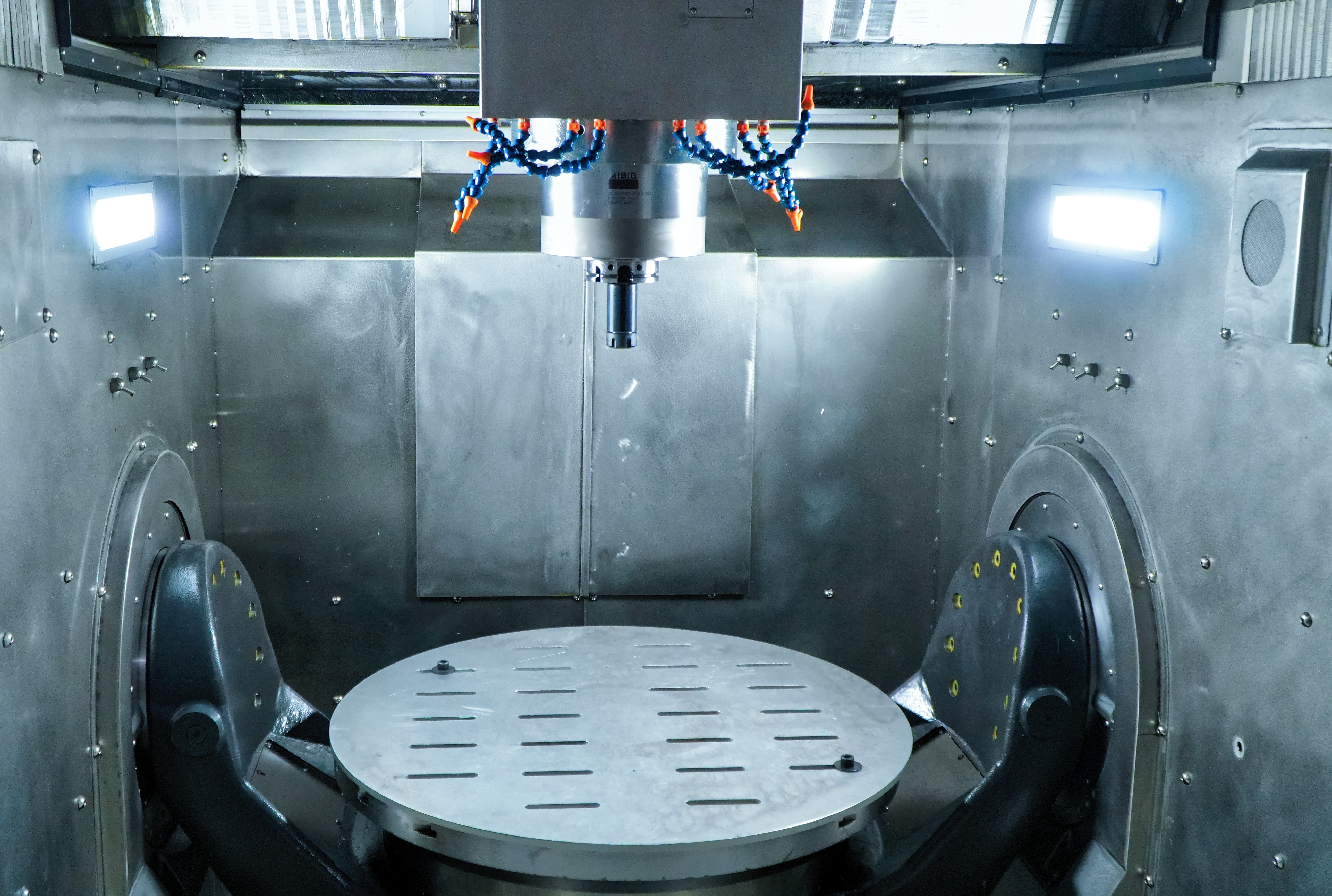
CMM Inspection: The Gold Standard for Verifying Precision CNC Parts
For checking dimensional accuracy in precision CNC parts, Coordinate Measuring Machines (CMMs) are still considered the gold standard by most manufacturers. These machines work through either tactile probes or optical scanners to map out intricate shapes and then check against CAD designs, spotting differences as small as a single micron. The importance of this becomes really apparent in industries such as aerospace and medical devices. A tiny measurement error here could mean disaster on the ground or inside someone's body. That's why these fields face intense oversight from standards like ISO 9001 and AS9100, which demand rock solid quality control at every stage of production.
Touch-Probe vs. Optical CMMs: Trade-offs in Speed, Resolution, and Suitability for High-Mix CNC Production
Touch probe CMMs can achieve really good accuracy around plus or minus 0.9 microns when measuring things like bearing seats and other flat surfaces but there's a catch. They take measurements one point at a time which means they're not so great when speed matters. On the flip side, optical CMM systems that work with lasers or structured light scan whole surfaces almost instantly. This makes them perfect for checking complex shapes and delicate thin walled components during initial production runs. But watch out for tricky materials. These optical systems often have trouble with shiny surfaces, see through materials, or those dark matte finishes that absorb all the light. For shops dealing with lots of different parts and frequent setup changes, combining both technologies works best. Start with optical scanning to spot any obvious issues across the whole component, then follow up with targeted touch probing on those specific areas controlled by GD&T tolerances. This two pronged approach typically saves about two thirds of the time compared to relying solely on traditional probing methods, while still maintaining reliable quality assurance throughout manufacturing.
Laser Calibration: Ensuring CNC Machine Tool Accuracy Before Cutting Begins
Most CNC machines experience some degree of drift over time because of things like heat changes, parts wearing down, and vibrations throughout the structure these problems build up even before any actual cutting happens. Laser calibration tools actually measure all those tiny geometry issues right at the start of production. They check for straight line errors, how much the machine tilts or turns (pitch, yaw, roll), and whether different axes are properly aligned across the entire workspace. Traditional ballbar tests just look at circular movements, but modern volumetric calibration goes further by tracking how multiple axes interact while simulating actual cutting operations. What this shows are tricky nonlinear errors such as when spindles drift in complex 5-axis setups, position shifts caused by metal expansion (sometimes around 0.05mm in steel when temperatures swing ±15 degrees Celsius), or when axes aren't perfectly perpendicular to each other. When manufacturers create custom compensation charts based on these findings, they can push positioning accuracy below 5 microns which stops dimensional problems before they ever reach the finished product.
API XD-Laser and FrogScan™ Flash Peel 3: Validating Volumetric Accuracy in Multi-Axis CNC Systems
Tools such as the API XD-Laser and FrogScan Flash Peel 3 allow for thorough calibration of multi-axis CNC machines in ways that go beyond basic checks. These devices don't take measurements one after another like traditional methods do. Instead, they work while the machine is actually moving through its normal operations, tracking things like how vibrations and structural bending impact accuracy when parts are being machined. What gets measured includes things like how straight the machine moves at different speeds, whether rotating parts stay stable, if axes remain properly aligned in three dimensions, and how the machine handles sudden changes in direction. The big difference here is that these tools catch errors that happen during actual operation rather than just sitting still. This leads to creating compensation models that get built right into the CNC control system itself. What happens next? Machines become much more reliable and precise over time. Manufacturers see fewer scrapped parts because potential problems with geometry get spotted early on, before any cutting even starts.
Closing the Loop: Real-Time In-Process Measurement for Precision CNC Parts
When manufacturers implement real time measurements during production, they shift quality control from something done after the fact to something that happens while making precision CNC parts. Putting sensors like laser scanners or fast touch probes right into the machining process lets them spot when dimensions start drifting off track. This can happen because machines heat up, tools gradually wear down, or materials just aren't perfectly uniform. The system then automatically adjusts the cutting path mid cycle, keeping tolerances really tight around ±0.005 mm most of the time. Factory stats show these systems cut down on wasted material by about 35% and boost initial success rates since problems get caught before finishing touches. There are still hurdles to overcome though, especially dealing with all that sensor data coming in fast and figuring out how to separate useful signals from background noise. But the payoff is worth it: faster production runs, fewer delays caused by fixing mistakes later, and better proof that products meet those tough specs required for critical components.
FAQ
What is GD&T?
GD&T, or Geometric Dimensioning and Tolerancing, is a system used by engineers to communicate precise information about the shape, size, and allowable deviation of parts to ensure they function correctly in their intended applications.
Why is dimensional accuracy important in CNC machining?
Dimensional accuracy is crucial as it affects the performance, reliability, and lifetime of the manufactured parts. Poor accuracy can lead to increased scrap rates, rework costs, and product failures.
What role do CMMs play in precision CNC machining?
CMMs, or Coordinate Measuring Machines, are used to verify dimensional accuracy by comparing the manufactured parts' geometry against the CAD designs, ensuring that any deviations are within acceptable limits.
What's the difference between touch-probe and optical CMMs?
Touch-probe CMMs measure one point at a time, providing high accuracy but at a slower pace. Optical CMMs use lasers or light to scan entire surfaces quickly but may struggle with reflective or transparent materials.
How does laser calibration improve CNC machine accuracy?
Laser calibration identifies geometric inaccuracies in CNC machines, allowing manufacturers to address issues before cutting begins, leading to greater accuracy and fewer dimensional problems in the final products.