Machine Calibration and Environmental Factors Affecting CNC Machining Tolerance
Spindle runout, axis misalignment, and backlash causing systematic dimensional drift
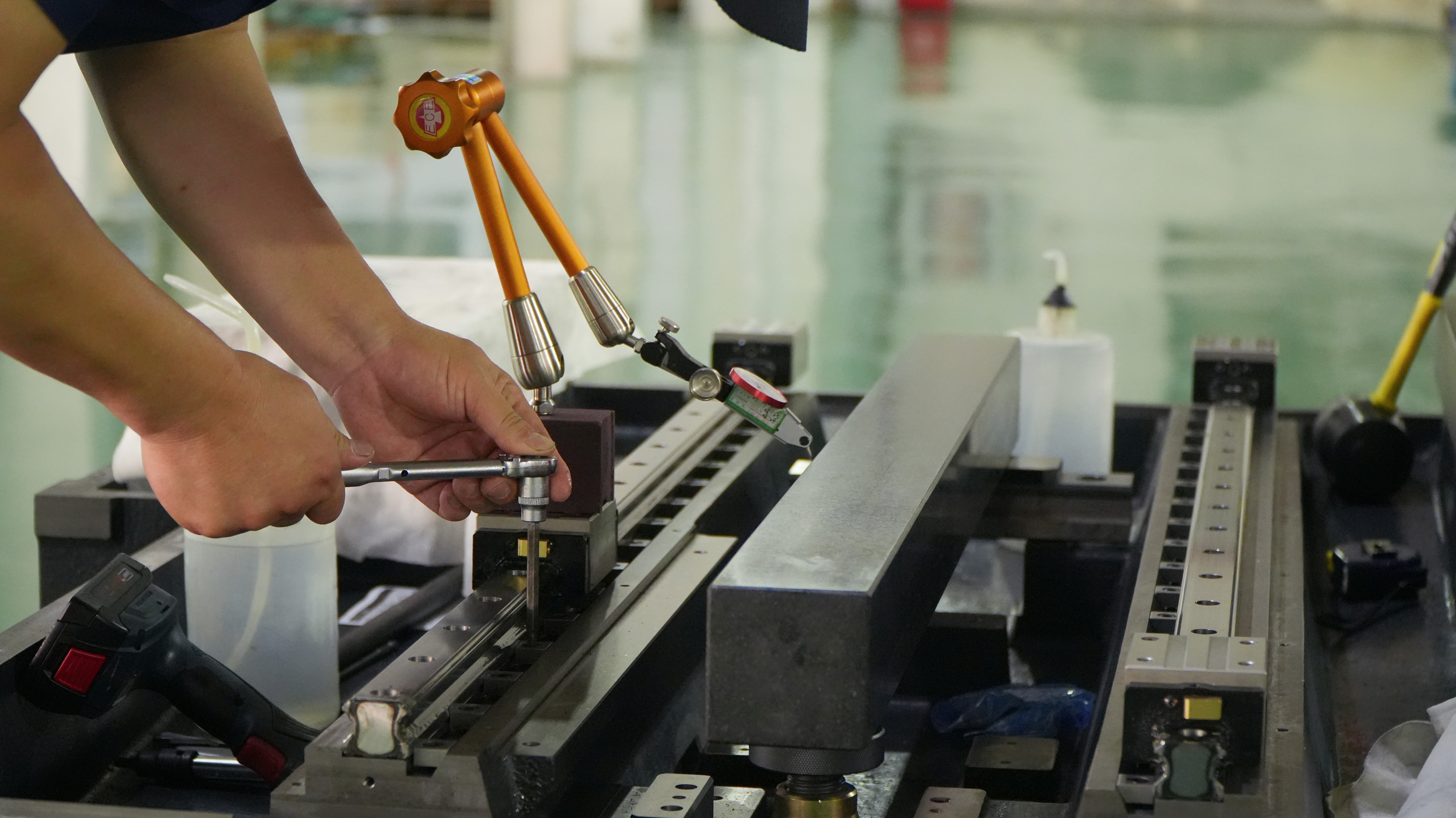
When a machine's spindle doesn't rotate perfectly around its center axis, it makes cutting tools less accurate. This problem usually starts with improper machine setup, which causes linear guides to drift off their intended path as they move. The result? Parts end up with distorted shapes that don't meet specifications. Another common issue comes from backlash in ball screw systems. These tiny delays happen every time the machine changes direction, and over time these small errors can add up to more than 0.1 millimeters across an entire production batch. If factories ignore these problems, studies show quality control failures go up by roughly 30 percent according to recent research published in engineering journals. To keep things running smoothly, most shops now rely on laser alignment checks combined with regular maintenance routines. This helps ensure consistent results down to about 5 microns of precision, which is critical for high tolerance manufacturing applications.
Thermal expansion and ambient temperature fluctuations undermining CNC machining accuracy
Temperature changes cause some serious problems when it comes to keeping things dimensionally accurate, but they're often overlooked in manufacturing settings. Steel structures and aluminum components tend to grow about 12 micrometers per meter for every degree Celsius increase. That means if a workshop experiences typical temperature swings of around 10 degrees during the day, a 400 millimeter component could end up shifting by as much as 0.05 mm - which is way beyond what's acceptable for aerospace specifications. The heat expansion of spindle bearings alone contributes roughly 40 percent to positioning mistakes in precision manufacturing operations. Smart factories tackle these issues by maintaining stable environments within plus or minus one degree Celsius and implementing specialized software solutions. These programs adjust cutting paths based on live sensor readings taken from key areas of the machinery, helping compensate for those pesky thermal variations that creep into production processes.
Tool-Related Errors That Compromise CNC Machining Precision
Worn, improperly selected, or unbalanced cutting tools introducing tolerance deviations
When tool wear goes unchecked, it accounts for roughly 25 to 30 percent of all machining problems according to research from Machining Science and Technology. Operators often overlook how dull cutting edges create uneven chip removal and hot spots on the workpiece, which can push dimensional tolerances past the critical ±0.05 mm range when working with hardened steels. Finishing operations using coarse grain carbide tools tend to generate unwanted vibrations that actually damage surface quality rather than improve it. The problem gets worse with unbalanced cutting tools. At high RPM speeds, centrifugal force starts pushing against both the tool itself and whatever part is being machined. This becomes particularly problematic during thin wall machining or when reaching into deep cavities where stability matters most.
Cutter compensation errors and tool deflection during high-load CNC milling operations
The way tools bend increases dramatically as the overhang gets longer, which really matters during those deep pocket cuts or complex contours. Take a standard 10 mm carbide end mill sticking out 50 mm for example. Under around 200 Newtons of force, this setup might actually flex by about 15 microns. That small amount of movement can lead to roughly 0.1 mm differences in the final shape when working with tough materials like titanium. Many computer-aided manufacturing programs still struggle to accurately predict these forces because they don't account properly for the actual angles where the cutting happens. This leads to bigger problems down the line as mistakes build upon each other. To keep things within acceptable tolerances, shops need to invest in systems that monitor loads while cutting and plan paths based on machine rigidity rather than relying solely on old fashioned offset charts.
Workholding Instability and Fixture-Induced Errors in CNC Machining
Soft jaw inaccuracies, chip buildup, and clamping-induced part distortion
Unstable workholding continues to be one of the main causes of scrap that could have been avoided. When soft jaws are made without considering how they'll actually fit the finished part, there's already misalignment right from the start. Chips building up between fixtures and parts create all sorts of problems too, since they make support inconsistent and allow tiny shifts during machining cycles. What really hurts quality though? Too much clamping pressure on delicate parts like thin walls or anything not very stiff. These parts get squished during machining, then spring back slightly once released, resulting in dimensions that don't meet specs even if everything else went perfectly. According to research published last year in Machining Science & Technology, these fixture issues cause around 15% of all preventable dimensional scrap in high precision manufacturing environments. To combat this problem, shops need to regularly remachine jaws using master reference parts as guides, install systems that automatically clear chips away during operations, and invest in hydraulic clamps that can adjust pressure based on real time feedback.
Programming, Setup, and Process Parameter Mistakes in CNC Machining
G-code Logic Flaws, Incorrect Tool Offsets, and Coordinate System Misalignment
Even a tiny mistake like a misplaced decimal point or failing to verify the coordinate system can push features off by plus or minus 0.005 inches, which often means scrapping what should have been a good part. When tool length or diameter offsets go wrong, the whole toolpath gets misaligned compared to what was programmed in the first place, leading to errors as big as 0.2 mm if nobody catches them early. Getting the Work Coordinate System right matters just as much. An incorrect Z-zero setting creates problems that spread through every operation after that. Most shops swear by touch probe checks and running full simulations before cutting into actual materials these days. According to industry reports, around 37 percent of all scrapped parts come down to missing steps during pre-production checks. That's why smart manufacturers stick to standard checklists, have two people double check those offset settings, and run dry runs without any workpiece loaded whenever possible.
Suboptimal Speed, Feed, and Depth-of-Cut Settings Amplifying Vibration and Surface Deviation
The way we set our cutting parameters really affects how stable things stay during machining, how much heat builds up, and ultimately how long our tools last before needing replacement. When spindle speeds get too high, they start exciting those resonant frequencies that can cause tools to deflect anywhere from 50 to 100 microns – not good for anyone wanting tight tolerances. On the flip side, if feed rates aren't sufficient enough, especially when working with tough materials like stainless steel or nickel alloys, we end up with work hardening issues. This leads to faster tool wear and surfaces that are roughly 30% rougher than desired. Getting depth of cut right matters too. Go too deep and we get chatter problems; go too shallow and it becomes rubbing instead of proper cutting action, neither of which gives us that nice smooth finish everyone wants. Finding optimal settings depends heavily on what material we're dealing with and the part geometry. For instance, titanium generally needs about 30% slower speeds compared to aluminum just to keep thermal distortion under control. Most shops now rely on sensor systems that monitor vibrations in real time so operators can tweak parameters as needed. And let's face it, nobody disputes that looking at chips coming off the workpiece tells us volumes about whether everything is running smoothly or if something needs adjusting.
FAQ Section
What is spindle runout and how does it affect CNC machining?
Spindle runout is when the machine's spindle does not rotate perfectly around its center axis, leading to inaccuracies in cutting tools and resulting in distorted parts that do not meet specifications.
How do ambient temperature fluctuations affect CNC machining accuracy?
Temperature changes cause materials like steel and aluminum to expand or contract, leading to dimensional inaccuracies in machined parts. This can be problematic in precision applications such as aerospace manufacturing.
Why is tool wear a significant issue in CNC machining?
Unchecked tool wear leads to uneven chip removal and hot spots, causing dimensional inaccuracies and quality issues, which can account for 25 to 30 percent of machining problems.
How can workholding instability cause errors in CNC machining?
Unstable workholding, such as soft jaw inaccuracies and chip buildup, leads to misalignment and shifts during machining, resulting in parts that do not meet specifications.
What role does programming play in CNC machining errors?
Programming errors, such as incorrect tool offsets and coordinate system misalignment, can lead to significant dimensional deviations and scrap parts if not caught early.