Geometric and Kinematic Foundations of Collision Risk in 5-Axis CNC Machining
Why Multi-Body Interference Is Inherent in 5-Axis Toolpath Planning
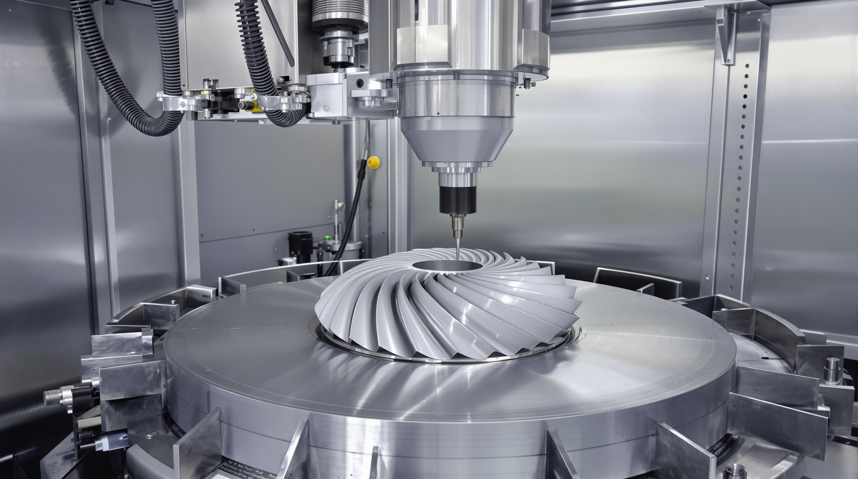
When working with 5 axis CNC machines, the freedom of movement along A B and C axes brings some serious challenges when it comes to avoiding collisions. These machines have five points of rotation compared to three in standard systems, which means the tool holder spindle and workpiece constantly interact in complex ways. Research back in 1992 showed something important about this technology. To keep things running smoothly without crashes, programmers need to run complicated checks on every single moving part. The cutting tools don't just reach out from their tips anymore they actually access parts from countless angles throughout their entire assembly. Imagine trying to tilt the spindle to get around the curve of a turbine blade. Sounds simple enough until suddenly the tool holder smacks into the fixture holding the part. According to a study published in Precision Engineering in 2009, almost half of all unexpected stoppages in aerospace manufacturing facilities happen because of these kinds of collisions while making intricate contours.
How Machine Kinematics, Axis Limits, and Tool Assembly Geometry Define Safe Motion Boundaries
Safe motion boundaries in 5-axis systems are governed by three interdependent physical constraints:
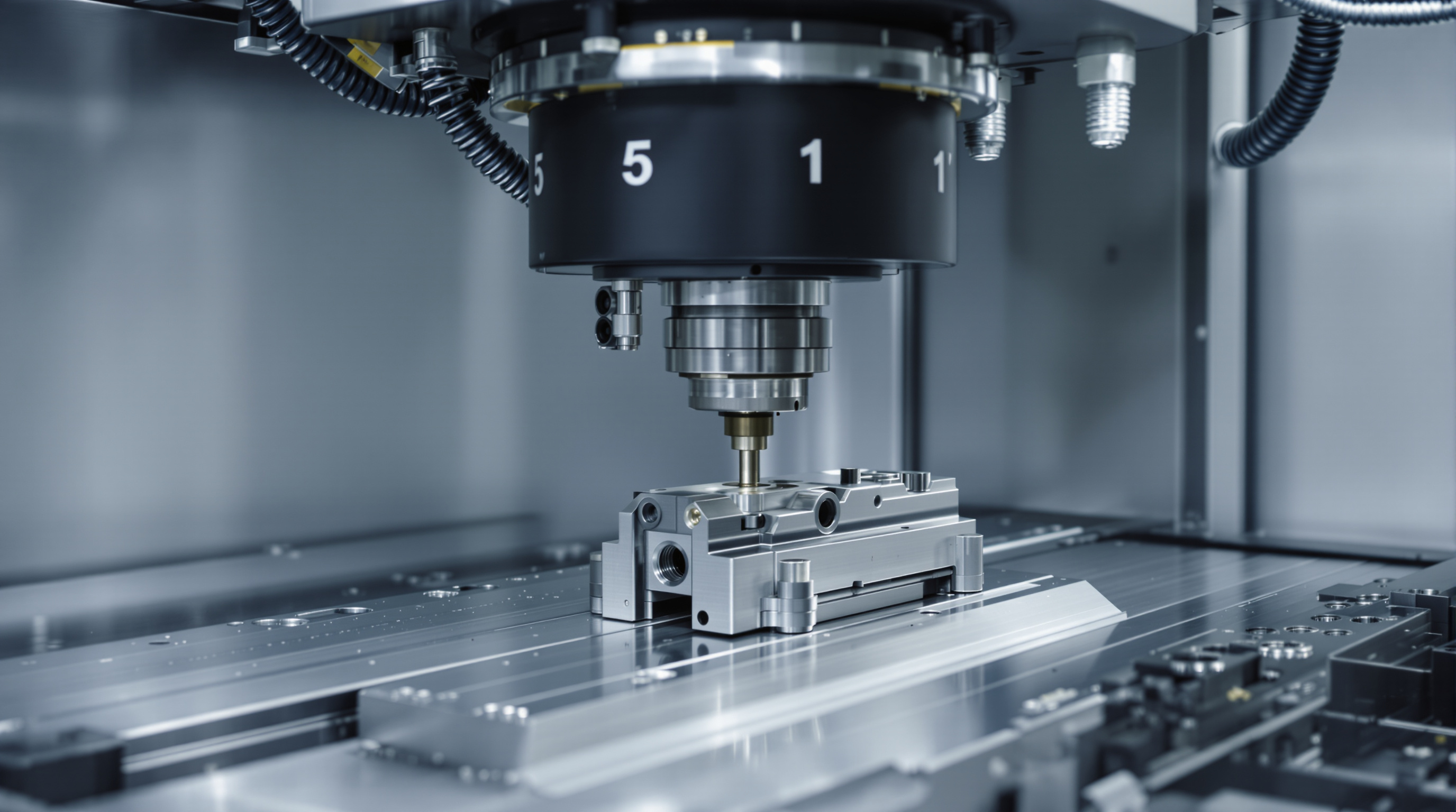
- Kinematic chain limits: Rotary axes operate within fixed angular ranges (typically ±30°–120°); exceeding them triggers mechanical interference.
- Tool projection geometry: Extended toolholders dramatically increase collision surface area—a 150mm extension raises impact risk by 68%, per the same 2009 Precision Engineering study.
- Dynamic clearance mapping: While CAM software approximates “swept volumes” (the 3D space traced by moving parts), physical validation remains indispensable due to modeling gaps in thermal drift, servo lag, and structural compliance.
When building machines, engineers build these limitations right into their kinematic models which help plan out movement paths, particularly near those tricky singularity points where all the axes line up and everything goes haywire or just stops working properly. A study from Computer Aided Design back in 2007 showed something pretty important too. They found that if there are calibration mistakes bigger than half a millimeter, things tend to fall apart completely. That's why getting the geometry right matters so much at every step when developing toolpaths for manufacturing processes.
Preventive Collision Avoidance via Intelligent Tool Path Optimization
Adaptive Tool Axis Control and Singular Region Avoidance
Smart toolpath optimization keeps tools from crashing into things not by locking them down, but rather by changing how they move around during machining operations. The system constantly tweaks the direction of the cutting tool to keep the best possible angle for cutting while avoiding anything in its way, basically remapping what areas are safe to work on as it goes along. What makes this method really effective is that it dodges those tricky spots called kinematic singularities. These happen when the rotating parts get too close together, causing tiny movements at the controls to result in big jumps in actual position. Research looking at how different machines handle their own specific movements shows that this kind of smart control cuts down dangerous collision areas by about 60 percent compared to old fashioned fixed paths. This means manufacturers can run their machines faster without worrying about breakdowns or damage to expensive equipment.
Case Evidence: A Leading Manufacturer's Collision Reduction Strategy
One major Chinese manufacturer specializing in precision engineering recently implemented advanced tool posture control systems throughout their entire 5-axis machining fleet. These systems combine real time tracking of machine axis positions with smart path corrections before collisions happen. After about 18 months on the shop floor, they saw something pretty impressive: collision incidents went down around 73% compared to what other companies typically experience. According to the Ponemon Institute's 2023 report on industrial downtime, this saved them roughly $740,000 each year in repairs and rework costs, plus it actually helped get better use out of their spindles. What's interesting is that product quality stayed just as good as before, even though they managed to boost average feed rates by about 22%. This shows that when machines know their own movements better, they can work faster without sacrificing safety or quality, which makes sense for any operation where mistakes cost money.
Reliable Collision Detection Using Integrated CAM Simulation and Digital Twin Validation
Moving Beyond Static Verification: Full-Assembly Simulation with Fixture, Holder, and Spindle Models
Traditional static verification methods that check just specific tool positions simply don't work well enough for 5-axis machining applications. Collisions often happen when parts are moving between rotating components, something basic checks miss completely. That's why modern computer aided manufacturing simulations take a different approach altogether. These systems create detailed models of everything involved in the process including fixtures, tool holders, spindles, actual workpieces, and even those pesky coolant nozzles that can cause problems if ignored. All these elements interact dynamically across the complete tool path. The simulation takes into account how axes behave unpredictably during tilting and rotation movements, what happens with metal expansion over long cutting periods, and how vibrations affect precision as material gets removed from workpieces. Shops that have implemented comprehensive assembly simulations see about a 73% drop in collision events according to recent industry data from 2023. This shows clearly that investing time in creating accurate virtual representations pays off handsomely in terms of real world safety improvements on factory floors everywhere.
Digital Twin–Driven Dynamic Kinematic Validation for Real-World Motion Fidelity
Digital twins extend simulation by closing the loop between virtual model and physical machine. By ingesting live sensor data—axis position, motor current, temperature, vibration—the twin continuously validates kinematic behavior under actual operating conditions. Where pure simulation assumes ideal performance, digital twin validation detects latent risks such as:
FAQ Section
What are the key challenges in 5-axis CNC machining?
The primary challenge in 5-axis CNC machining is managing the increased potential for collisions due to the machine's wide range of motion across five axes. This requires detailed planning and optimization of tool paths.
How do intelligent tool path optimization techniques help in collision avoidance?
Intelligent tool path optimization techniques help avoid collisions by dynamically adjusting the machine's movements and avoiding kinematic singularities, ensuring safer and faster machining processes.
What is a digital twin in the context of CNC machining?
A digital twin is a real-time virtual model of a physical machine, which continuously monitors and validates kinematic behavior by using live data, allowing for effective collision detection and risk mitigation.