What Surface Tolerance Really Means in Precision Machining
Beyond Ra: Understanding PV, RMS, Slope Error, and Form Deviation
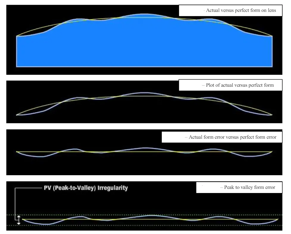
When talking about surface tolerances, we're looking at much more than just Ra values, which measure average roughness. Take PV for instance Peak to Valley measurements tell us about those extreme differences between high spots and low areas on a surface. This matters a lot in sealing applications because sometimes one tiny 4 micrometer bump can lead to leaks in hydraulic systems, even if the Ra number looks good at around 0.8 micrometers. Then there's RMS Root Mean Square calculation that gives us an average based on all those little peaks and valleys across the surface. Engineers find this particularly useful since it relates better to actual performance factors like contact pressure and component lifespan compared to Ra alone. Slope error is another important parameter that checks how straight or curved different parts of a surface are against what was intended in design specifications. This becomes absolutely essential when manufacturing things like lenses or airplane wings where every degree counts. Finally, form deviation tells us whether the whole shape of a manufactured part stays true to its original CAD design blueprint. It's not enough for individual spots to look right the entire contour needs to match expectations too.
Why ±1–5 Microns Demands Integrated Control of Geometry, Texture, and Stability
Achieving micron-level tolerances requires simultaneous, tightly coordinated control of three interdependent domains:
- Geometry: Adherence to GD&T specifications ensures dimensional and positional accuracy across features like bores, flanges, and datum surfaces.
- Texture: Surface asperity distribution governs tribological behavior—wear resistance, lubricant retention, and micro-crack initiation under cyclic loading.
- Stability: Thermal drift, mechanical vibration, and material stress relaxation must be actively mitigated; otherwise, parts may meet nominal dimensions at inspection but fail in service due to time- or temperature-dependent distortion.
Aerospace turbine blades exemplify this integration: texture influences boundary-layer airflow efficiency, geometry ensures rotor-stator clearance and assembly fit, and thermal stability prevents micro-cracking during rapid thermal cycling. Compliance with any one parameter—without balancing the others—does not guarantee functional reliability.
How Precision Machining Processes Achieve Sub-Micron Surface Tolerance
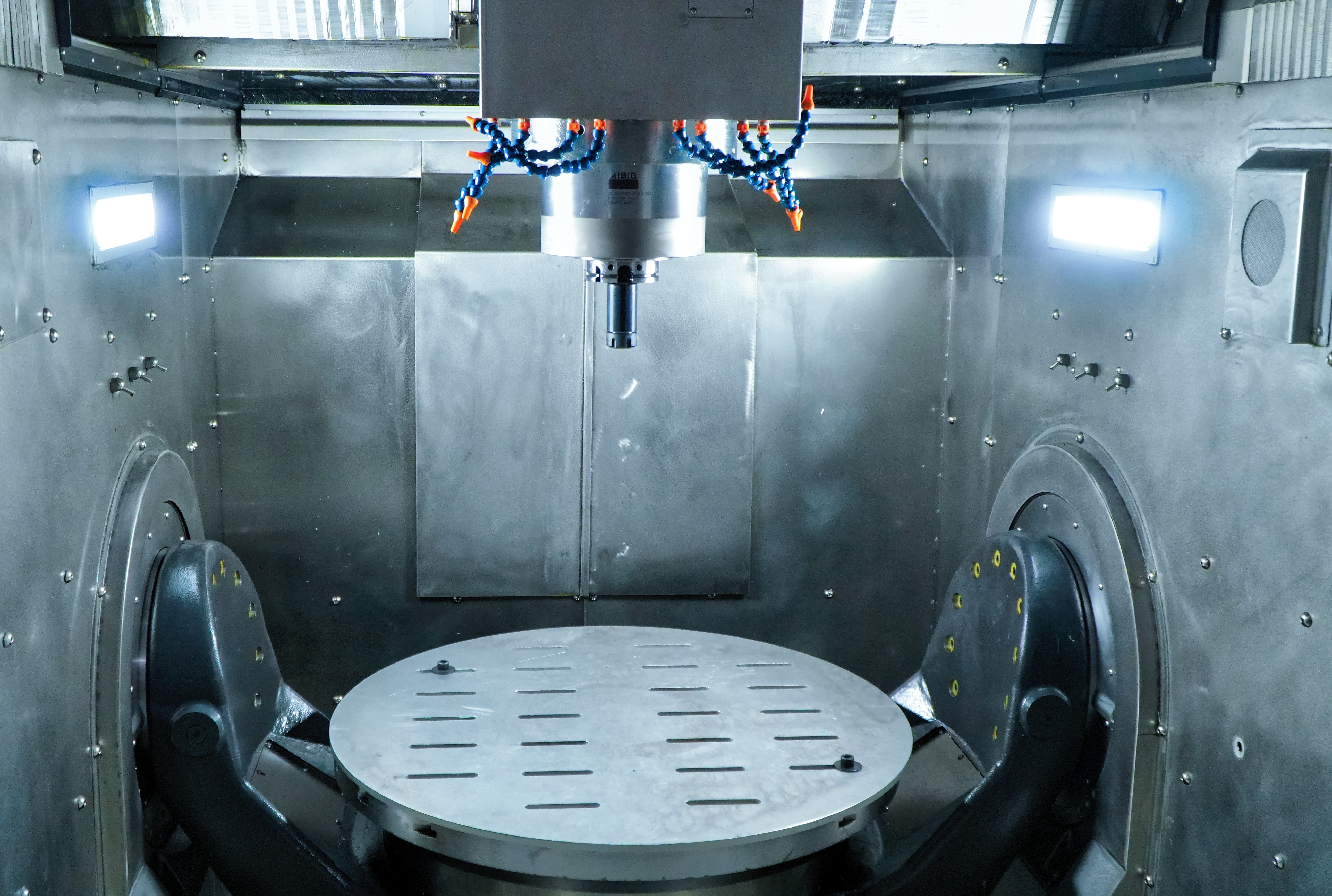
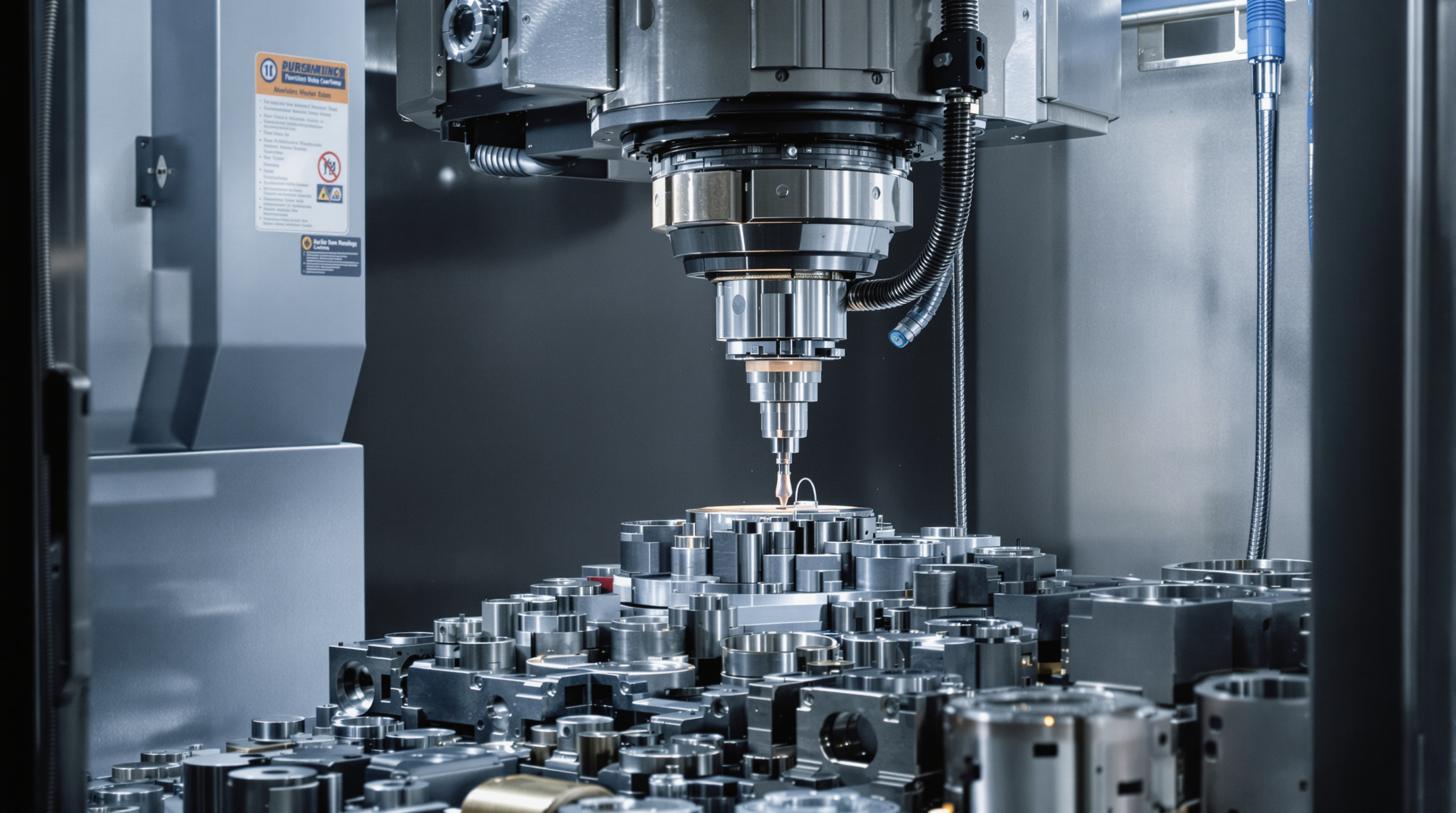
CNC Machining: GD&T-Driven Setup, Thermal Compensation, and In-Process Monitoring
CNC machining today can produce surfaces with sub-micron consistency thanks to multiple layers of control strategies. Geometric Dimensioning and Tolerancing (GD&T) plays a big role here, guiding how fixtures are designed, datums selected, and toolpaths sequenced. This helps minimize those annoying cumulative errors that tend to creep in during multi-axis operations. Thermal compensation systems work in real time too, constantly adjusting for when spindles and machine structures expand. Steel expands about 10 microns per meter per degree Celsius after all, so even small changes in room temperature need correction just to maintain that tight ±2 micron geometric control. Touch-trigger probes come into play during actual machining cycles, checking key dimensions as work progresses. These measurements allow operators to make adjustments on the fly before mistakes get worse. The result? Consistent surface finishes below 0.8 microns Ra even on complicated freeform shapes that would challenge simpler equipment.
Precision Grinding Innovations: ELID, Creep-Feed, and Adaptive Dressing for Ra < 0.02 µm
Modern precision grinding can achieve surfaces almost as smooth as optics thanks to three key advancements working together. The first is Electrolytic In Process Dressing, or ELID for short. This technique keeps grinding wheels sharp by electrochemically stripping away bonding materials right during operation. What does that mean? Stable cutting action and surface finishes below 0.02 microns on tough materials like hardened steel and ceramic parts. Then there's creep feed grinding, which takes big bites out of workpieces in one go (think anywhere from 0.1mm to 30mm depth). This approach cuts down those pesky entry/exit marks and stops ripples from forming when machines resonate at certain frequencies. And finally we have adaptive dressing algorithms that constantly reshape grinding wheels based on what they hear and measure in real time, adjusting for changes in material hardness while keeping abrasive grains exposed properly. Put all these methods together and manufacturers see fewer problems with both large scale shape errors and tiny texture irregularities across their finished products.
| Process | Surface Finish (Ra) | Key Innovations | Thermal Stability Impact |
|---|---|---|---|
| CNC Machining | < 0.8 µm | Real-time thermal compensation | ±2 µm/°C drift control |
| Precision Grinding | < 0.02 µm | ELID, adaptive dressing | ±0.5 µm/°C drift control |
Validating Surface Tolerance: Metrology Strategies for Traceable Precision Machining
On-Machine Probing vs. CMM vs. Optical Profilometry: Accuracy, Speed, and Uncertainty Tradeoffs
Getting those micron level surface tolerances right requires matching up the measurement technique with what actually matters functionally. On machine probing gives instant feedback as parts get made, which cuts setup time somewhere around 30 to 50 percent. But there's a catch - thermal drift happens and so do machine kinematic errors, so we're looking at about plus or minus 2 microns of uncertainty. Coordinate Measuring Machines. CMMs for short, deliver much better geometry accuracy, down to half a micron, particularly when dealing with those tricky 3D datum points and form features. The downside? They need climate controlled environments and can triple the overall cycle time. Optical profilometry is great for non contact texture analysis with resolutions as fine as Ra 0.01 microns. but it runs into problems with anything steeper than 70 degrees slope angle, shiny surfaces, or transparent materials because signals just disappear or create interference patterns. When working on critical aerospace parts or implant quality medical devices, most shops use a mixed approach these days. Start with some in situ probing then follow up with complete CMM certification. This combination knocks down measurement risks by roughly 18% and keeps everything compliant with ISO/IEC 17025 standards. Basically, it's about balancing speed where possible against necessary precision in real world manufacturing situations.
Material and Environmental Realities: Why Surface Tolerance Isn’t Just About the Machine
Thermal Drift, Vibration Isolation, and Cleanroom Protocols for Stable Micron-Level Results
Getting micron level surface tolerances right requires strict environmental control. Thermal drift is really the biggest problem for precision machining work. When ambient conditions fluctuate too much, aluminum parts can deform by over 5 microns per meter while standard steel might stretch around 12 microns per meter. These numbers blow past the usual plus or minus 2 micron tolerance requirements. Keeping temperatures stable within half a degree Celsius across both machining areas and measurement stations helps eliminate this issue entirely. Vibration control matters just as much though. Shops typically use either active air tables or passive seismic mounts to isolate machinery from floor vibrations. Anything above 10 Hz starts messing with cutting forces and creates those annoying surface waves we all try to avoid. Cleanrooms rated at ISO Class 7 or higher keep dust particles from embedding themselves in softer materials or scratching up finished surfaces. Maintaining humidity between 40 to 55 percent also stops certain composite materials and plastics from expanding when they absorb moisture. Without all these environmental safeguards in place, even state of the art machines struggle to consistently hit those tight 1 to 5 micron tolerances manufacturers demand.
Material-Specific Responses: Aluminum, Invar, and Fused Silica in Tight Tolerance Regimes
How materials behave really sets the boundaries for what's possible with surface tolerances and determines what adjustments need to happen during processing. Take aluminum for instance. Its thermal expansion rate is pretty high at around 23 micrometers per meter per degree Celsius. That means manufacturers have to manage heat aggressively and keep machining cycles short and controlled to prevent parts from warping or changing shape. Then there's Invar, which contains iron and about 36% nickel. This alloy expands very little when heated, only about 1.2 micrometers per meter per degree Celsius. While this makes it great for maintaining dimensions, it has another problem. The material gets easily affected by vibrations, creating those annoying surface waves. So shops working with Invar need super rigid setups and systems that dampen out low frequency vibrations. Fused silica presents yet another challenge. It responds almost nothing to temperature changes. below 0.5 micrometers per meter per degree Celsius, but it breaks so easily. Getting surfaces down to less than 0.05 micrometers roughness requires careful control of feed rates, special diamond tools, and coolants that won't react chemically with the material. And don't forget about coolant choices either. Aluminum works best with lots of flood cooling to carry away heat quickly, whereas fused silica needs something much gentler like minimal quantity lubrication or even dry grinding techniques to maintain its structural integrity. Understanding all these different behaviors isn't just about knowing what machines can do. It's actually about respecting the fundamental physics of materials themselves. When engineers take this approach, they end up with parts that consistently meet those tight micron level specifications time after time.
FAQ Section
What is surface tolerance in precision machining?
Surface tolerance in precision machining refers to the allowable level of deviation from a specified surface finish. It encompasses not just roughness values like Ra, but also extreme differences in high and low spots (PV), average deviation (RMS), curvature errors (slope error), and overall shape consistency (form deviation).
Why is thermal drift a concern in precision machining?
Thermal drift can cause parts to expand or contract significantly based on temperature changes, leading to inaccuracies in micron-level tolerances. Stable environmental conditions are crucial to maintaining precision.
What role does material choice play in achieving micron-level surface tolerances?
Different materials have different thermal expansion rates and vibration responses, impacting surface tolerances. Aluminum expands significantly, Invar is vibration-sensitive, and fused silica's brittleness requires careful handling and specific coolants.
How are precision machining tolerances validated?
Precision machining tolerances are validated using various metrology techniques such as on-machine probing, CMMs, and optical profilometry, each offering its own tradeoffs in terms of accuracy and speed.