Understanding Chatter Mechanisms in 5-Axis Milling Operation
Regenerative Chatter Dynamics Under Multi-Axis Tool Engagement and High Spindle Speeds
Regenerative chatter happens when vibrations from cutting create waves on the surface of whatever is being worked on. These waves get picked up again by the tool as it moves across them, setting off a kind of feedback loop that keeps going. With 5 axis milling, things get even more complicated because the tool is rotating while moving through space at the same time. This creates constantly changing conditions for how the tool interacts with the material - sometimes thicker chips form, other times thinner ones, and the forces acting on everything keep shifting around too. At really high speeds, say over 15,000 RPM, these small changes can lead to big problems. The vibrations start matching up with the natural frequencies of the whole machine setup, causing those annoying self-starting oscillations we all know and hate. What follows isn't pretty: cutting forces go wild, surfaces end up looking terrible instead of smooth, and tools wear out much faster than they should according to research papers published in machining journals. And worst of all? Sometimes this harmonic alignment just hits suddenly, making machines unstable without any prior signs.
How Non-Orthogonal Kinematics Distort Cutting Force Harmonics and Destabilize Stability Boundaries
When tools aren't positioned at right angles during complex 5-axis machining operations, they throw a wrench into standard chatter prediction models. Most traditional stability theories work under the assumption that forces act straight on and engagement remains constant, but in reality, 5-axis machines constantly tilt and rotate throughout their cuts. This movement changes everything from cutting edge angles to where chips actually go and how forces spread out across different machine axes. What happens next? The harmonic patterns get messed up pretty badly. Cutting force frequencies start spreading out instead of staying focused, and when tools tilt differently, these frequencies jump around all over the place. The relationship between vibrations also becomes unpredictable chaos rather than following expected patterns. Practically speaking, this means stability limits for machining drop somewhere around half compared to what we see in basic 3-axis setups. Some recent studies published in CIRP Annals back this up, showing how changing engagement angles scatter vibrational energy across various frequency ranges. While this spreads out energy away from those sharp resonance points, it creates instability problems across wider operating ranges too.
Optimizing Cutting Parameters Using Stability Lobe Analysis for 5-Axis Milling Operation
Adapting stability lobe diagrams to variable tool orientations and feed directions
For 5 axis milling work, stability lobe diagrams need constant adjustment since both tool orientation and feed directions keep changing as the machine moves along its path. Three axis operations have fixed immersion angles and consistent chip loads, but things get complicated when working with five axes. The toolpaths here bring about major changes in geometry. Chip thickness varies, force vectors point different directions, and those radial and axial depths aren't what they seem anymore at each position update. Research published in the CIRP Annals back in 2023 showed something important too standard SLDs without adjustments can actually suggest stable cutting depths that are up to 40% too high in these multi axis situations. Getting this right means several things need attention:
- Segment-wise lobe recalculations using real-time engagement geometry (e.g., instantaneous tilt, lead, and roll angles)
- Compensation for gyroscopic effects at spindle speeds >15,000 RPM, which alter modal stiffness and damping
- Orientation-aware mapping of stability zonesâprocess simulation shows maintaining â¥12° tool axis deviation during contouring preserves lobe prediction accuracy within ±8%.
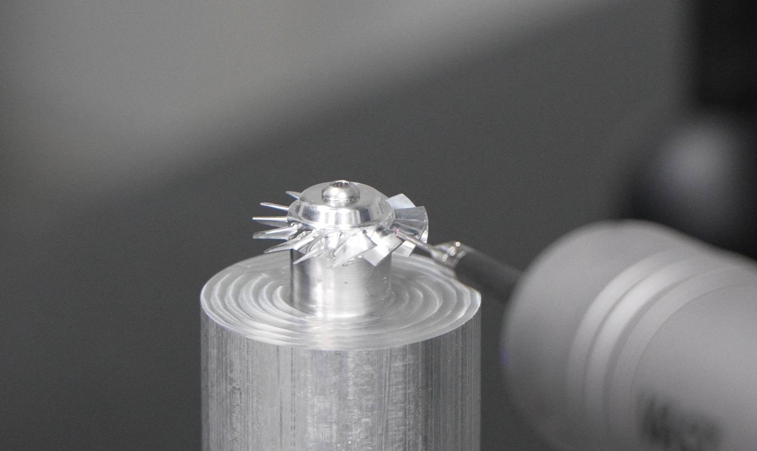
Case validation: 22% chatter reduction via lobe-guided speed/depth selection (DEPU CNC)
An aerospace company specializing in high-precision components implemented real time stability lobe guidance during machining operations for titanium impellers using their DEPU CNC system. They adjusted spindle speeds throughout the process, running at around 15,200 RPM when making radial cuts and dropping to approximately 14,300 RPM during axial movements. This approach led to a noticeable reduction in chatter amplitudes by about 22 percent, along with a 30% decrease in surface harmonic content down to Ra values below 0.6 micrometers. The depth of cut in stable machining areas went up from 0.6 mm to 0.85 mm after validation tests, all while keeping tool deflection well within acceptable limits at less than 8 micrometers. Overall cycle times were shortened by nearly 20%, yet dimensional accuracy stayed within strict +/- 15 micrometer specifications. These results clearly show how applying physics based parameters can boost both production efficiency and product quality simultaneously.
Vibration-Suppressing Toolpath Strategies for 5-Axis Milling Operation
Trochoidal and Constant Chip Thickness Paths for Uniform Load Distribution in Continuous 5-Axis Contouring
Trochoidal cutting paths and those that maintain constant chip thickness help prevent chatter because they keep the forces applied to the tool much more stable. When using 5 axis machining, these methods spread out how the tool engages with material along its cutting edge, so each part of the cutter gets similar workloads even when dealing with complicated shapes. This kind of even distribution actually stops vibrations before they start, which matters a lot when working at high speeds on parts that are either very thin or just not stiff enough to handle rough cutting. Some shops also implement adaptive tool rolling techniques that improve this consistency even more. These approaches smooth out sudden changes in direction as tools move from one section to another, helping protect both the spindle and whatever holds the cutting tool together.
Entry Strategy Impact: Rolling vs. Plunge â Quantified 37% Peak Acceleration Reduction
How parts enter the machining process really affects how they respond dynamically at first. When using plunge entry, there's this big sudden impact that hits the material hard and causes lots of different vibrations at once. This can be a real problem when working with flexible components or parts with deep cavities. On the other hand, controlled rolling entry works differently. It brings the tool into contact with the material slowly over time. Industry tests show this method cuts down peak acceleration by about 37%. And guess what? That means less chatter happens, tools last longer, and surfaces come out better quality overall. Most top aerospace companies and medical device makers have started requiring their shops to use rolling entry techniques for important 5 axis finishing jobs. Especially when cutting through tough materials like titanium, Inconel, or even regular aluminum where those annoying resonances can wreck parts before they're done.
Mechanical System Optimization: Toolholding, Rigidity, and Fixturing for 5-Axis Milling Operation
Controlling vibrations during 5-axis milling really comes down to getting three main areas right together. Let's start with toolholding. The goal here is to keep overhang as short as possible while ensuring the connection between tool and holder stays solid. Hydraulic or shrink-fit chucks actually cut down on radial tool deflection by around 40% when compared to regular collets during those fast contouring operations, which makes a big difference in how stiff the whole system feels. Next up is checking structural rigidity through actual testing rather than just theory. Manufacturers need to measure natural frequencies across different tool positions to spot potential resonance issues throughout the entire machine-workpiece-tool chain, not just looking at standard setups. Fixturing brings us to our third point. Good fixtures need to handle vibrations actively. Modular designs with viscoelastic layers can soak up unwanted harmonic energy without losing position accuracy even when dealing with complicated rotational forces. According to recent research from the Journal of Manufacturing Processes, about 78% of all vibration related scrap happens because fixtures aren't stiff enough. For thin wall parts used in aerospace applications, putting strain gauges on key clamp points becomes crucial. These sensors kick in when movement goes beyond 5 micrometers, helping catch chatter problems before they become serious. And last but definitely not least, matching taper classes matters a lot. When there's a mismatch like using a CAT40 holder in a BT30 spindle, it creates vibration harmonics that are three times stronger once speeds hit 15,000 RPM or higher. Getting these specifications aligned properly forms the bedrock of stable 5-axis machining operations.
FAQ
What is regenerative chatter in 5-axis milling?
Regenerative chatter occurs when vibrations from the cutting process create waves on the surface of the material being worked on. These initial waves then get picked up by the tool again, creating a feedback loop that sustains the vibration. This is further complicated in 5-axis milling due to the rotating and spatial movement of the tool.
How does non-orthogonal kinematics affect cutting in 5-axis milling?
In 5-axis milling, when tools are not positioned at right angles, they disrupt standard chatter prediction models. This means that the geometric changes in tool orientation affect cutting force harmonics and destabilize stability boundaries, often reducing stability limits drastically.
Why are stability lobe diagrams important in 5-axis milling?
Stability lobe diagrams (SLDs) are crucial because they help adjust for the variable tool orientations and feed directions seen in 5-axis milling. Without adjustments, SLDs might inaccurately suggest stability, potentially leading to tool and surface damage.
What strategies can help suppress vibrations in 5-axis milling?
Using trochoidal paths and maintaining constant chip thickness can help distribute the load evenly across the tool's edge, preventing chatter. Entry strategies, like rolling instead of plunge, also play a significant role in reducing vibration and tool wear.
How can toolholding and fixturing optimize 5-axis milling operations?
Minimizing tool overhang and ensuring firm toolholder connections with systems like hydraulic chucks can significantly decrease radial tool deflection. Additionally, modular fixturing designs can absorb unwanted vibrations, increasing system stiffness and accuracy.