
Gap check: Confirm the parts are suitable before purchasing.
The specifications sheet will list the stroke, table size, and maximum workpiece size. Even if these three requirements are met, it is entirely possible that the part cannot be machined because these figures do not describe the configuration that your process actually requires.
The failure mode remains consistent. The part was quoted based on its bounding box. Upon machine delivery, during the initial angle setting, it was discovered that the tool holder collided with the support at the required tilt angle. The purchase order has been signed; the problem has now become a fixture issue.
Four clearances determine whether a part is suitable. All four clearances can be checked before placing an order. 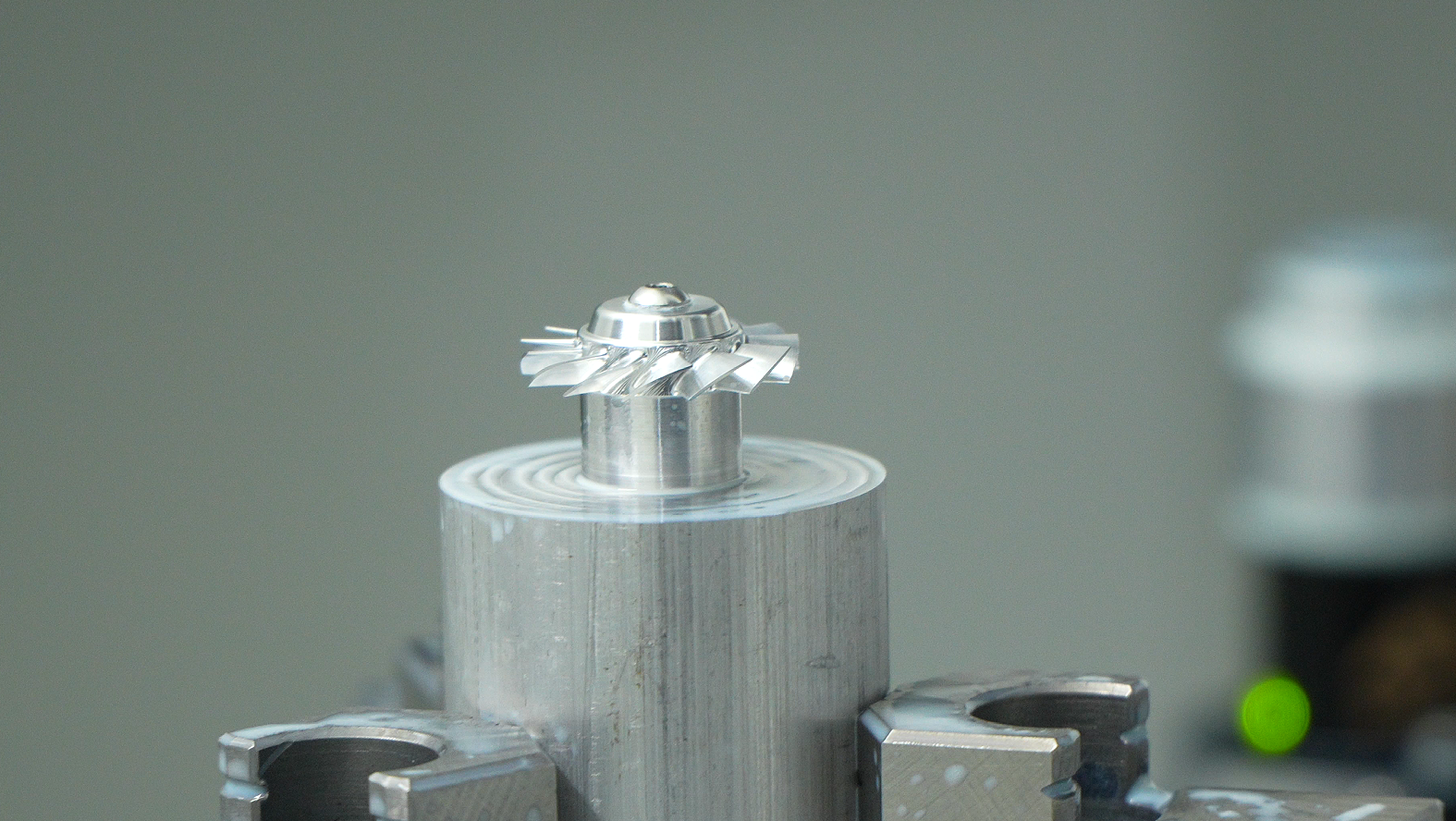
Clearance 1 — The distance from the spindle nose to the worktable; the angle must meet the requirements.
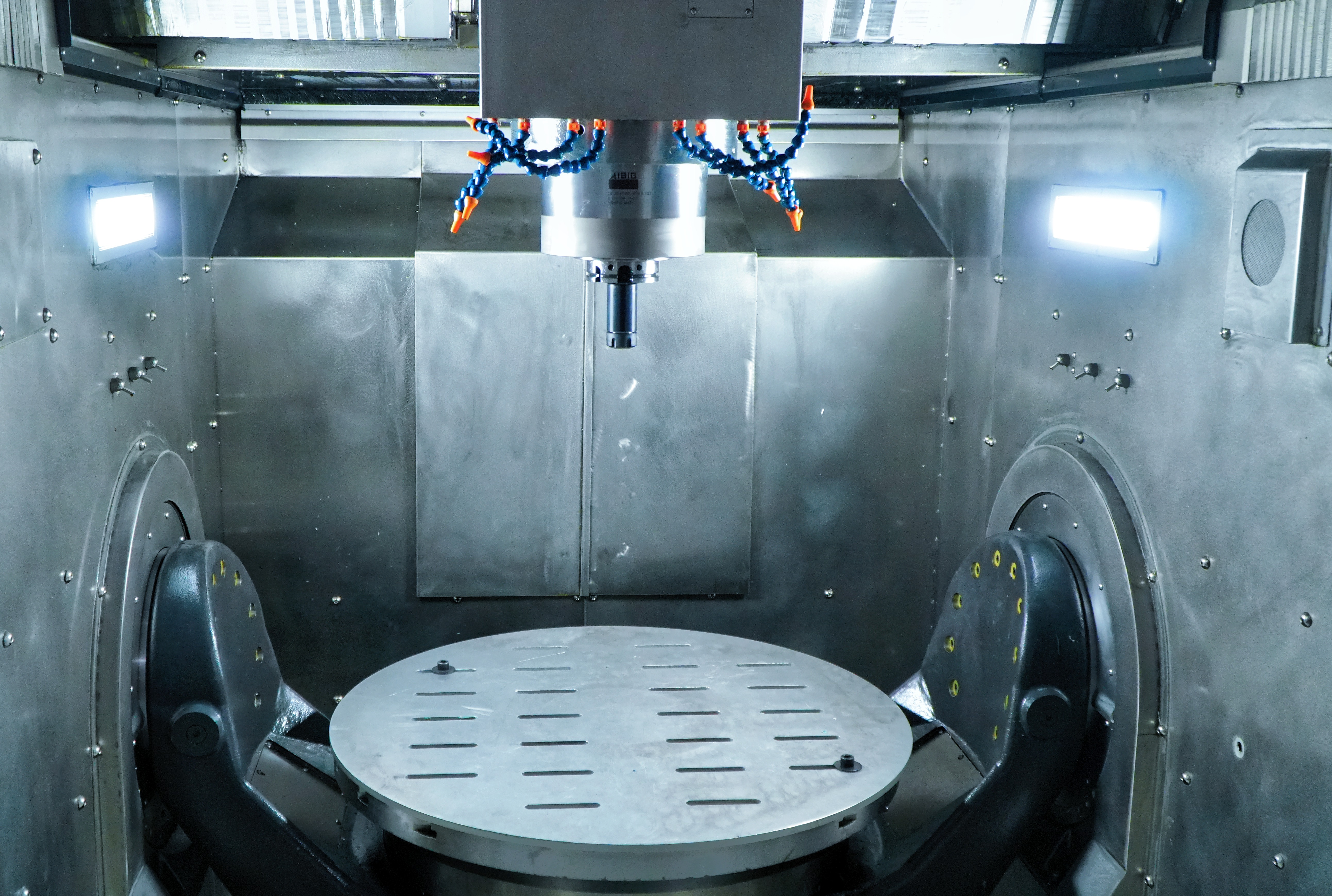
This is the most frequently overlooked figure in comparisons. It is not the travel distance, but the vertical distance between the spindle gauge plane and the worktable surface. On rotary machine tools, it defines the vertical range within which the workpiece and fixture must be located.
|
G300 |
G630 |
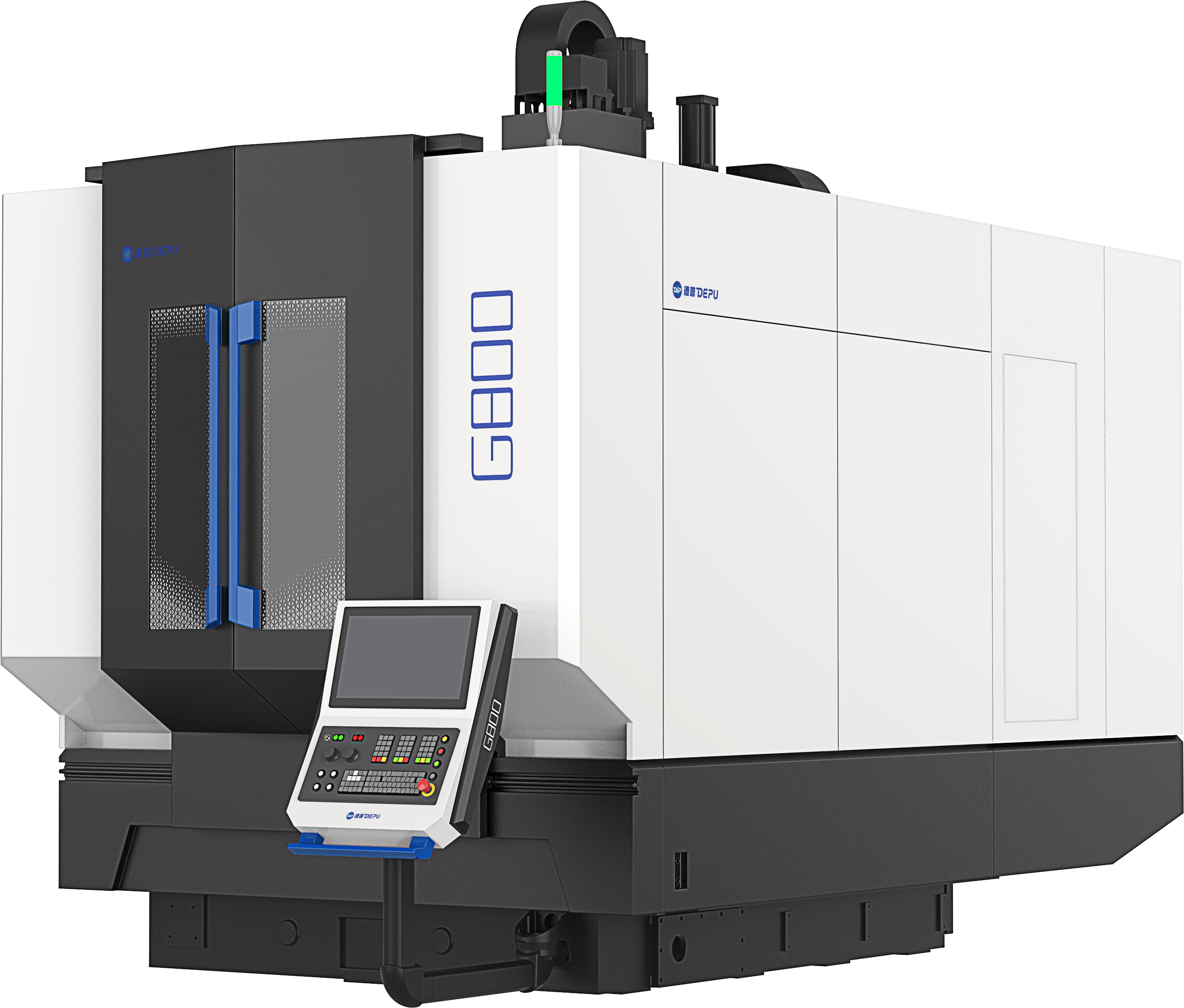
G800 |
|
|
spindle nose to table |
≈145–445 mm |
175–675 mm |
225–825 mm |
Carefully read the G300 instruction line. A total vertical travel of 300 mm sounds ample, but after deducting the fixture height, it becomes insufficient. With 90 mm thick fixtures stacked, the usable height is only 210 mm, and the workpiece must avoid the bracket when rotating along the A-axis. Even if the travel data specified on the drawings seems fine, actual machining often fails.
The inspection does not measure the part height itself, but rather the part height plus the fixture height, measured along the machine tool's Z-axis at the maximum tilt angle specified in the process plan. For tilt features, the effective height is greater than the part's nominal height because tilting rotates the diagonal to the vertical direction.
The measurement method differs for large tilting head machine tools because it is the spindle, not the workpiece, that rotates. The distance from the spindle nose to the worktable is 200–1200 mm for the U1000 and U1250, 50–1250 mm for the U1600, and 200–2000 mm for the U2000. These three machine tools also publish the distance from the spindle center to the worktable in horizontal mode—80–1080 mm for the U1000 and U1250, and 150–1350 mm for the U1600—this value determines the interference with the workpiece when the spindle rotates below horizontal. Comparing rotary head machine tools to tilting head machine tools requires different measurement methods and cannot be directly compared.
Gap 2 — Sweeping envelope at both ends
The maximum workpiece size in the datasheet is indicated by a single number—Ø390×250 mm, Ø700×400 mm, and Ø900×500 mm for the G series. This value describes a range of workpiece sizes under specific operating conditions. When the A-axis is fully deflected, the scanned volume of the workpiece changes, and corner points that were originally within the scanned volume may go outside the range when the carriage rotates.
The A-axis range varies across different product lines, so this is more important than it appears on the surface:
● G300 — A axis ±120°, symmetrical. The cradle swings with the same amplitude in both directions.
● G630 and G800 — A-axis +30° to −130°. Asymmetrical design, with a larger range below horizontal.
If your process requires parts to rotate to a large positive angle, the symmetrical G300 rotation range offers more flexibility. If critical features are facing downwards, a larger negative rotation range on a larger machine tool is more suitable. When comparing axis rotation ranges, refer to the angles actually required by the process, not just the widest-looking range.
The geometry of the U-series machine tools (https://www.depu.com/products/u-series) differs. The workpiece does not rotate; the spindle tilt angle is approximately 210°, so interference is caused by the spindle head rotating around the fixed workpiece, rather than by the workpiece rotating within the carriage. This design generally offers greater tolerance for machining large workpieces, which is why this series of machines can machine workpieces weighing up to 8000 kg. For structural details on this design, please refer to How the U-series machine tool structure achieves micron-level accuracy (https://www.depu.com/blog/depu-u-series-machine-structure-micron-accuracy) .
One more point to note: the rotation range is relative to a certain reference point, and different documents may give the same physical range from different zero-point positions. Before initial setup, be sure to confirm the convention for the rotation direction and the positive rotation direction with the machine tool manufacturer and your post-processor.
Gap 3 – tools, not just parts.
The workpiece is just one of two objects moving within the working range. When a long tool moves at a steep angle, it is usually the first factor to cause interference, and the tool limitations that determine this situation are independent of the stroke parameters.
|
G300 |
G630 |
G800 |
U1000 |
U1250 and above |
|
|
tool diameter |
Ø75 / Ø100 mm* |
Diameter 75 / Diameter 120 mm* |
Diameter 125 / Diameter 150 mm* |
110/200 mm |
110/200 mm |
|
Maximum tool diameter |
— |
300 mm |
400 mm |
— |
— |
|
Maximum tool length |
200 mm |
300 mm |
300 mm |
350 mm |
400 mm |
|
Maximum tool weight |
5 kg |
8 kg |
14 kg |
20 kg |
15 kg |
Larger numbers are suitable when adjacent pockets are empty.
This will have three practical consequences.
Tool length is a hard and fast rule, not an option. On the G300 machine tool, the maximum tool length is 200 mm. For deep cavity machining, long tools may be unusable, leading to a change in the process plan, not the machine tool selection. Please compare this value with the longest tool length in your CAM settings.
Tool weight indirectly limits feed rate. Heavier end mills or boring tools limit cutting force, thus affecting machining cycle time. Note the weight limitations of U-series tools: the U1000 can use 20 kg tools, while the larger U1600 and U2000 can use 15 kg tools, due to the different design priorities of the latter two.
Adjacent tool slots will occupy tool magazine space. Larger tool diameters are only suitable when adjacent tool slots are empty. If your machining program alternates between large face mills and many small tools, then having an excessively large tool size of one type in the tool magazine may occupy multiple available tool slots.
Gap 4 — Fixture height and reference chain
Fixture clearance is the most often overlooked aspect in dimensional discussions, and it can account for twice the production capacity.
Vertically, jig stacking directly reduces the available distance between the spindle and the worktable. Hydraulic or zero-point positioning systems occupy 90 to 150 mm of space before workpiece mounting.
In terms of mass calculation, the mass of the workpiece being held will affect the rated load of the worktable because the rated load describes the rotational mass on the axis of rotation, not the lifting capacity.
|
G300 |
G630 |
G800 |
U1000 |
U1250 |
U1600 |
U2000 |
|
|
Maximum table load |
50 kg |
850 kg |
1200 kg |
1800 kg |
2500 kg |
4,000 kg |
8000 kg |
On the G300 machine tool, this interaction is particularly severe. A 12 kg clamp reduces the workpiece's load capacity to 38 kg, while a workpiece originally rated at 45 kg now exceeds the machine tool's capacity. This problem would not occur if 20% to 30% of the rated load were reserved for workpiece clamping during the dimensional measurement stage.
There's a second layer of factors to consider in multi-faceted machining. Single-setup strategies are typically used to avoid repositioning heavy parts, as explained in the article " Why 5-axis machining can be completed in one go but requires three setups" (https://www.depu.com/blog/why-use-3-setups-when-5-axis-cnc-can-do-it-in-one) . However, this advantage depends on the fixture's ability to remain stable throughout the part's entire range of motion without needing to be re-clamped—which in turn depends on the aforementioned clearance. If the clearance is insufficient during tilting, it cannot be called a single-setup solution.
An example, and data that is missing from every data manual.
Take a workpiece measuring 350 × 350 × 220 mm and mount it on a 90 mm fixture plate on a G300 machine tool. The dimensions appear appropriate: when placed vertically, the assembly height is 310 mm, and the spindle-to-table travel range of the G300 is 145 to 445 mm. With the spindle retracted, there is a 135 mm clearance above the workpiece. Everything seems fine.
Now tilt it.
The dimensions of the portion rotating about axis A are 350 mm x 220 mm. The diagonal length of this portion is:
√(350² + 220²) = 413 mm
Therefore, as the part tilts, its vertical height increases from 220 mm to 413 mm, an increase of 193 mm. Adding the 90 mm clamping force, the top of the part is 503 mm from the mounting plane, exceeding the maximum height limit of 445 mm for the G300 spindle nose. The part, originally placed upright, can no longer be placed upright once tilted according to the process plan, and the limiting factor is not from the load, but from its geometry.
There is a noteworthy issue with this calculation. The part rotates about the center of axis A, not about its base, and this center height is not listed in any standard specification table. Therefore, the above calculation only tells you the severity of the problem, not the final conclusion: enough to let you know that a vertical increase of 193 mm needs to be checked, but not enough for you to sign off on it.
A reliable method is to obtain the center height of axis A from the layout drawing, design the machine in CAD based on the actual geometry, and check the assembly from various angles in the process flow diagram. This process takes about an afternoon to complete the machine procurement and is a crucial step in identifying discrepancies between order specifications and actual requirements.
Pre-purchase checklist
Compare these eight checks to the largest and most geometrically complex sections of the book, rather than to the average:
13. At the maximum tilt angle, the angle between the workpiece plus fixture height and the distance from the spindle nose to the worktable window.
14. The scan envelope is located at the largest angle A or B in the process plan, not at the zero angle.
15. Adjust the tilt axis range to each angle according to the process plan requirements.
16. The ratio of the longest tool length to the machine tool's maximum tool length in CAM settings.
17. Compare the maximum tool diameter with the magazine capacity limit, and consider the influence of adjacent empty tool positions.
18. Comparison of the heaviest tool component and tool weight limits
19. The ratio of the total mass of the part and fixture to the rated load of the worktable should be reserved for a load of 20% to 30%.
20. The correspondence between the rotation axis convention, positive rotation direction, zero reference, and the post-processor.
If the machine fails checks 4 through 8, process planning is required. If it fails checks 1 through 3, machine selection is required—and now it's much cheaper to identify the problem.
For process-level techniques on maintaining tool-workpiece clearance at extreme angles, refer to Tool Orientation Optimization in Complex Surface Machining (https://www.depu.com/blog/tool-orientation-optimization-in-complex-surface-machining) . Regarding machine size selection, the G-series (https://www.depu.com/products/g-series) and U-series (https://www.depu.com/products/u-series) pages provide complete travel and envelope data, while the section on how workpiece size and weight affect machine selection (https://www.depu.com/blog/workpiece-size-weight-5-axis-machine-selection) covers the relevant framework.
Please provide geometric figures, not just price ranges.
Before recommending a machine tool, you can submit a quotation request including part drawings, required fixtures, and process plan angles so that we can verify it based on the machining range. Please send your inquiry request through the DEPU inquiry page (https://www.depu.com/inquiry) , specifying the distance from the spindle nose to the worktable and the scanning range at your required angle. Model data: G300 ( https://www.depu.com/product/g300 ) , G630 ( https://www.depu.com/product/g630 ), G800 ( https://www.depu.com/product/g800 ), U1000D ( https://www.depu.com/product/u1000) .
————————————————————————————
*The specifications shown are for configuration reference only and may vary depending on the option package. Please confirm the final product specification sheet before submitting a quote. Workpiece fixture design and CAM post-processing configuration should be based on the actual machine tool drawings.