Understanding Interference Constraints in Complex Surface Machining
Geometric sources of tool–surface and tool–holder interference
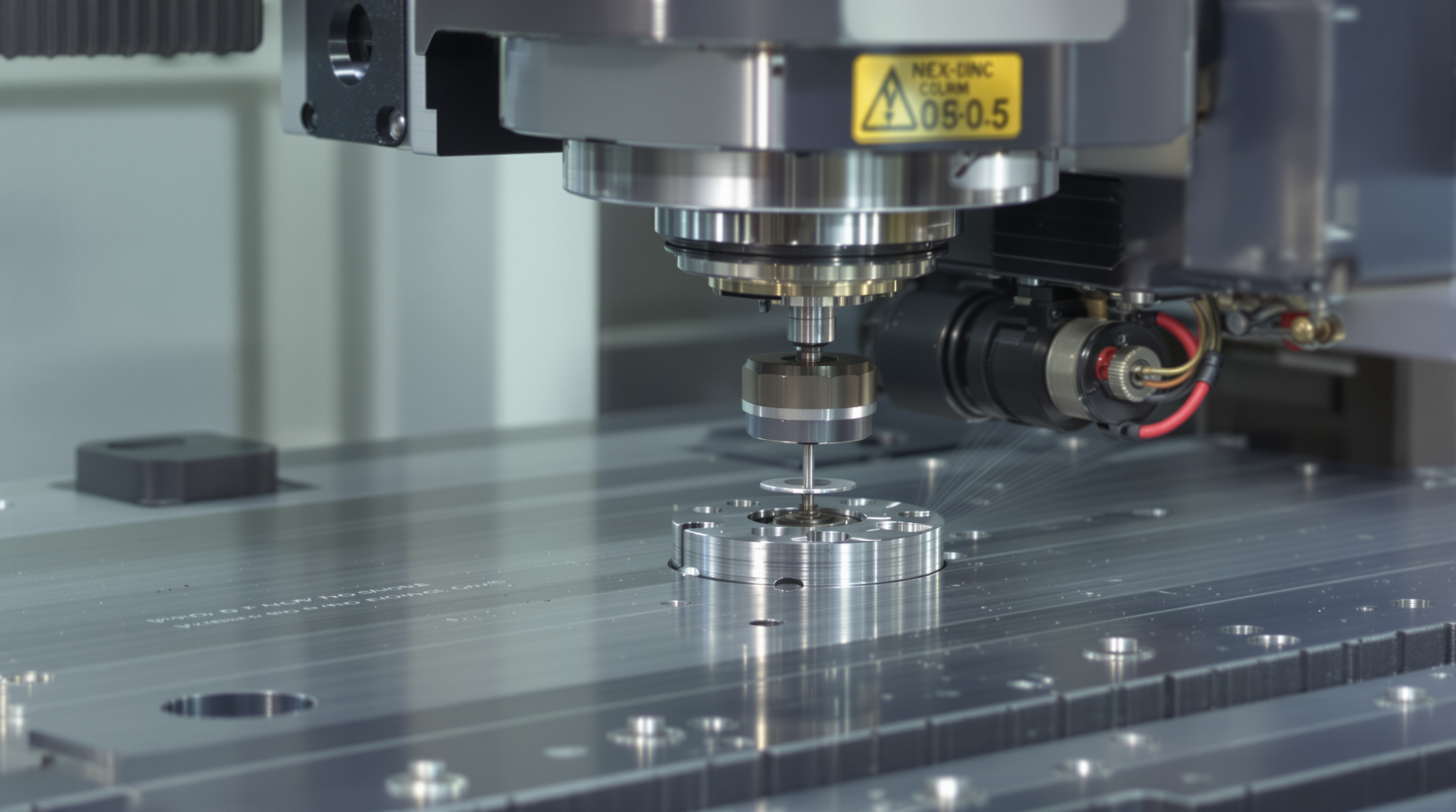
When tools collide with surfaces or their holders during complex surface machining, these problems become major roadblocks for manufacturers. Sometimes the problem comes down to geometry mismatches where things like ball nose radii don't match up with what's happening on the actual part being machined, which leads to those annoying gouges everyone tries to avoid. At the same time, tool holders often hit nearby features because there just isn't enough space in those deep pockets or around steep walls. Take turbine blades for instance. Machinists need to stay clear of parts by about half a millimeter or so while keeping everything stable and rigid enough to do proper cutting. Things get even trickier when using short tool extensions since there's less room between the tool and vertical walls. Complex curves that push beyond what tilting can handle, plus all those moving parts in 5 axis machines, really pile on the challenges for anyone trying to avoid collisions during production runs.
C-space representation and identifying feasible orientation domains
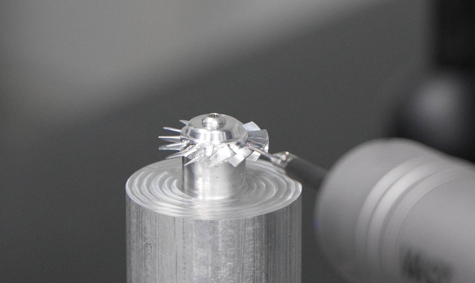
When working with Configuration Space (or C-space) mapping, what we're really doing is turning those pesky interference constraints into something engineers can actually calculate and work with. The trick lies in visualizing tool axis vectors as points scattered across a unit sphere. This approach helps identify areas where tools won't collide, basically simplifying complicated geometry problems down to manageable angular ranges. Take aerospace impeller machining as an example. Around the blade roots, tilt angles generally stay within about 60 to 70 degrees. But things get really tight near those hub junctions where there's barely any room to move around. That's where visibility cone algorithms come in handy. These smart methods cut down on collision checks dramatically, saving roughly 89% of the time compared to old school brute force approaches according to a study published in the ASME Journal back in 2023. All this computational speed makes real time decisions possible when selecting orientations, allowing manufacturers to strike that delicate balance between cutting material quickly, maintaining surface quality, and keeping everything mechanically safe during operation.
Curvature-Driven Tool Orientation Strategies for Complex Surface Machining
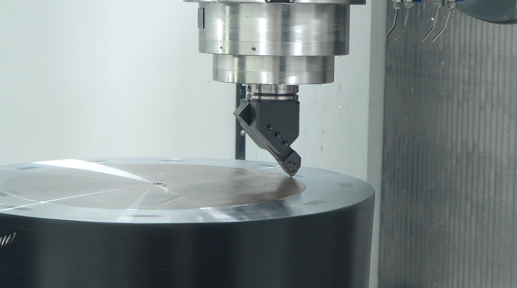
Aligning cutter axis with local surface curvature to minimize deviation
Getting the best results from cutting tools starts with matching the cutter's spin direction to how curved the part actually is. When we line up the tool this way, it cuts much closer to what was intended on paper. Think of it like following the natural shape rather than fighting against it. Most computer programs these days use advanced math to figure out exactly how to angle and position the tool at every spot where it touches the material. They look at the curves in real time and adjust accordingly. This approach works really well for complicated shapes found in things like airplane engines or pump parts. Shops that switch from old fixed-angle methods report around a 40% drop in measurement errors, which makes a big difference when precision matters most.
Balancing gouging avoidance, surface fidelity, and machining efficiency
Getting good results from high performance machining means dealing with three main issues at once: avoiding gouges and crashes, keeping surfaces smooth, and getting things done quickly enough. When machinists go too cautious with their setup, they avoid problems for sure, but end up wasting about 25 to 30 percent extra time because of all those extra passes and slower speeds. On the flip side, going too aggressive can lead to tool holder collisions when working on deep parts, plus the surface finish suffers badly, often making those Ra numbers creep past 0.8 microns. The solution? Multi objective optimization techniques help find middle ground here. They work by setting boundaries around where tools can move safely, keeping stepovers controlled so Ra stays under 0.4 microns, and adjusting feed rates as needed to get maximum cutting done. For shops in aerospace or precision mold making, these optimizations actually pay off handsomely. A standard improvement of around 15% in overall machining speed cuts down production costs by roughly $18k per batch, all while still meeting those tight ±0.01 mm tolerance requirements that are so critical in these industries.
Computational Methods for Optimal Feasible Tool Orientation Selection
Sampling-based search versus analytical C-space optimization
Picking the best tool orientations that avoid collisions is really about choosing between two main approaches: sampling-based searches or analytical C-space optimization. The sampling method breaks down orientation space into discrete parts and checks for interference randomly. It works fast and handles weird shapes well, but there's always a chance we miss better solutions between those sample points. On the other hand, analytical methods calculate exact math boundaries for what orientations work, using geometric constraints. These give guaranteed results within certain limits, but come at a cost of heavy computation power, particularly when dealing with complex NURBS surfaces. Real world tests have shown that analytical techniques can hit around 0.05mm accuracy on turbine blades, though they take roughly three to five times longer than sampling methods. Most shops actually combine both strategies these days. They start with quick sampling to narrow down possibilities, then switch to analytical methods for fine tuning until they get that sub-micron level of precision. This mixed approach cuts path generation time by about 78% while still meeting the strict requirements needed for critical parts.
Industrial Validation of Adaptive Tool Orientation in Real-World Complex Surface Machining
Tests in actual manufacturing settings show that tools oriented based on part curvature consistently deliver better results in tough production scenarios. Most manufacturers see around 18 to 22 percent less machining time, about 30 percent extended tool life, and significant improvements in surface finish down to Ra 0.2 microns these days. Traditional fixed axis approaches just can't match this kind of performance. The secret lies in constantly adjusting the tool position according to the geometry being cut, maintaining ideal cutting conditions even on complex freeform shapes while still keeping things safe from gouging incidents. A major aerospace company recently cut their scrap rate by nearly half when making turbine blades after implementing real time orientation adjustments, clearly showing how precise algorithms lead directly to better yields. This approach works wonders particularly well with thin walled components and hard metals, areas where standard tool paths often run into problems with vibration, bending, and heat related distortions. What we're seeing now is that these carefully designed orientation techniques work just as well in real workshops as they do in computer simulations, giving shops both better quality parts and lower costs overall.
FAQs about Interference Constraints in Complex Surface Machining
What are interference constraints in machining?
Interference constraints in machining are issues that arise when tools collide with surfaces or holders during the machining process, often due to geometric mismatches or insufficient space around features.
How does C-space mapping help in machining?
C-space mapping helps by visualizing tool axis vectors as points, identifying areas where tools won't collide, and simplifying geometry problems into manageable ranges.
What is the advantage of curvature-driven tool orientation?
Curvature-driven tool orientation involves aligning the tool's axis with the part's curvature to reduce deviation, resulting in better cutting and reduced measurement errors.
How do analytical methods compare to sampling methods in tool orientation?
Analytical methods provide precise calculations for optimal tool orientations, while sampling methods offer quicker, albeit less precise, solutions. Combining both can yield effective results.
Why are adaptive tool orientations beneficial in manufacturing?
Adaptive tool orientations adjust in real-time based on component geometry, leading to reduced machining time, extended tool life, and improved surface finishes.