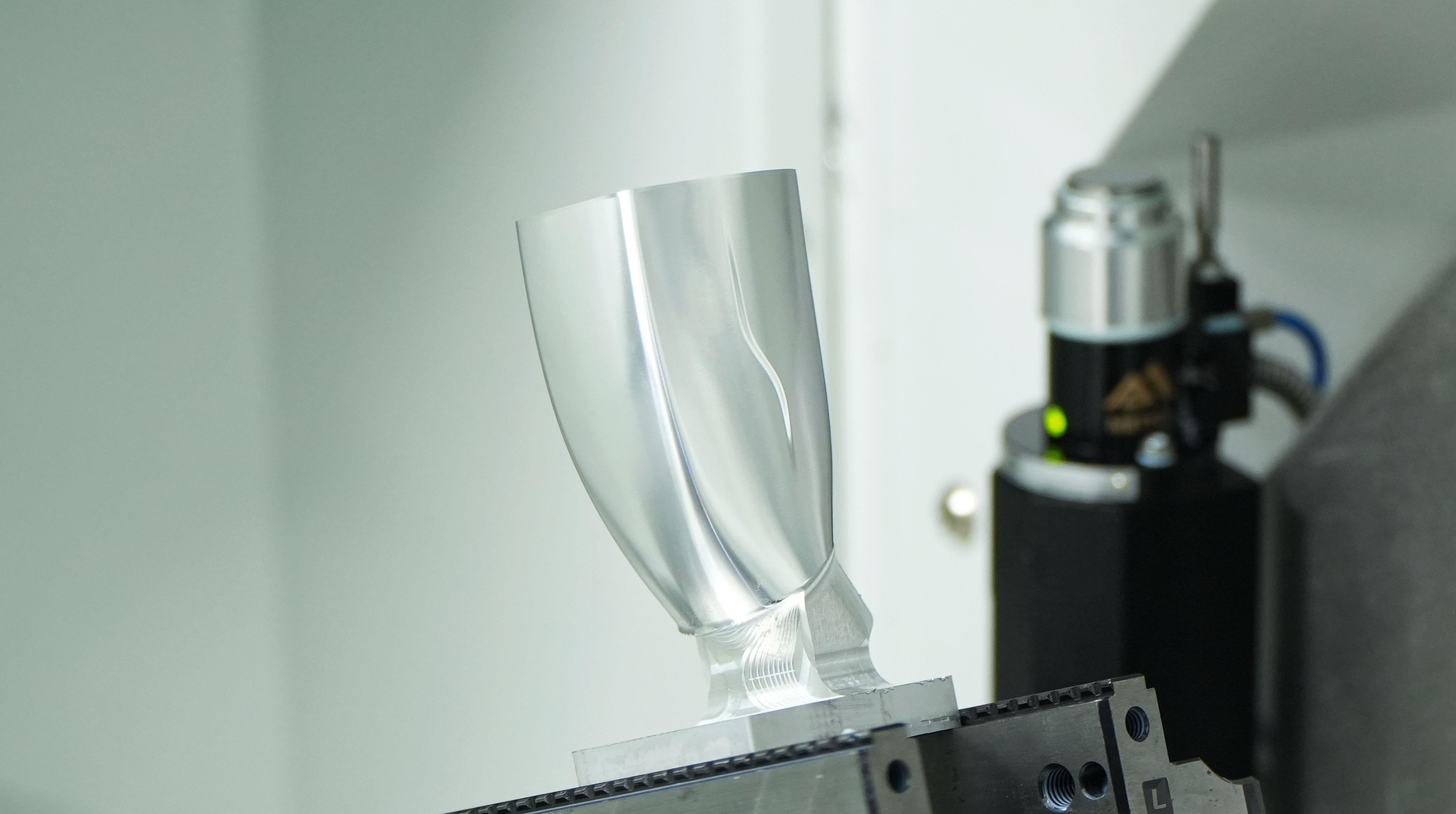

How to Program a 5 Axis CNC Machine: Complete Step-by-Step Guide
Programming a 5 axis cnc machine is one of the most technically demanding skills in modern precision manufacturing. Unlike 3-axis machining, where the cutting tool moves along X, Y, and Z linear paths, a 5 axis cnc system adds two rotational axes — typically labeled A and B, or A and C — allowing the spindle and workpiece to be repositioned continuously during a single setup. This fundamental difference means that the programming logic, toolpath strategies, and post-processing requirements are substantially more complex, and getting them right requires a structured, step-by-step approach.
For engineers, machinists, and production managers stepping into 5 axis cnc programming for the first time — or looking to sharpen their existing workflow — this guide breaks the entire process into clear, logical stages. From understanding your machine kinematics and preparing your CAD model, to configuring your CAM software, verifying toolpaths, and running the first cut safely, each step builds on the last. Whether you are machining aerospace components, medical implants, complex molds, or precision mechanical parts, mastering 5 axis cnc programming will directly improve your part quality, reduce setup time, and expand the range of geometries your shop can confidently produce.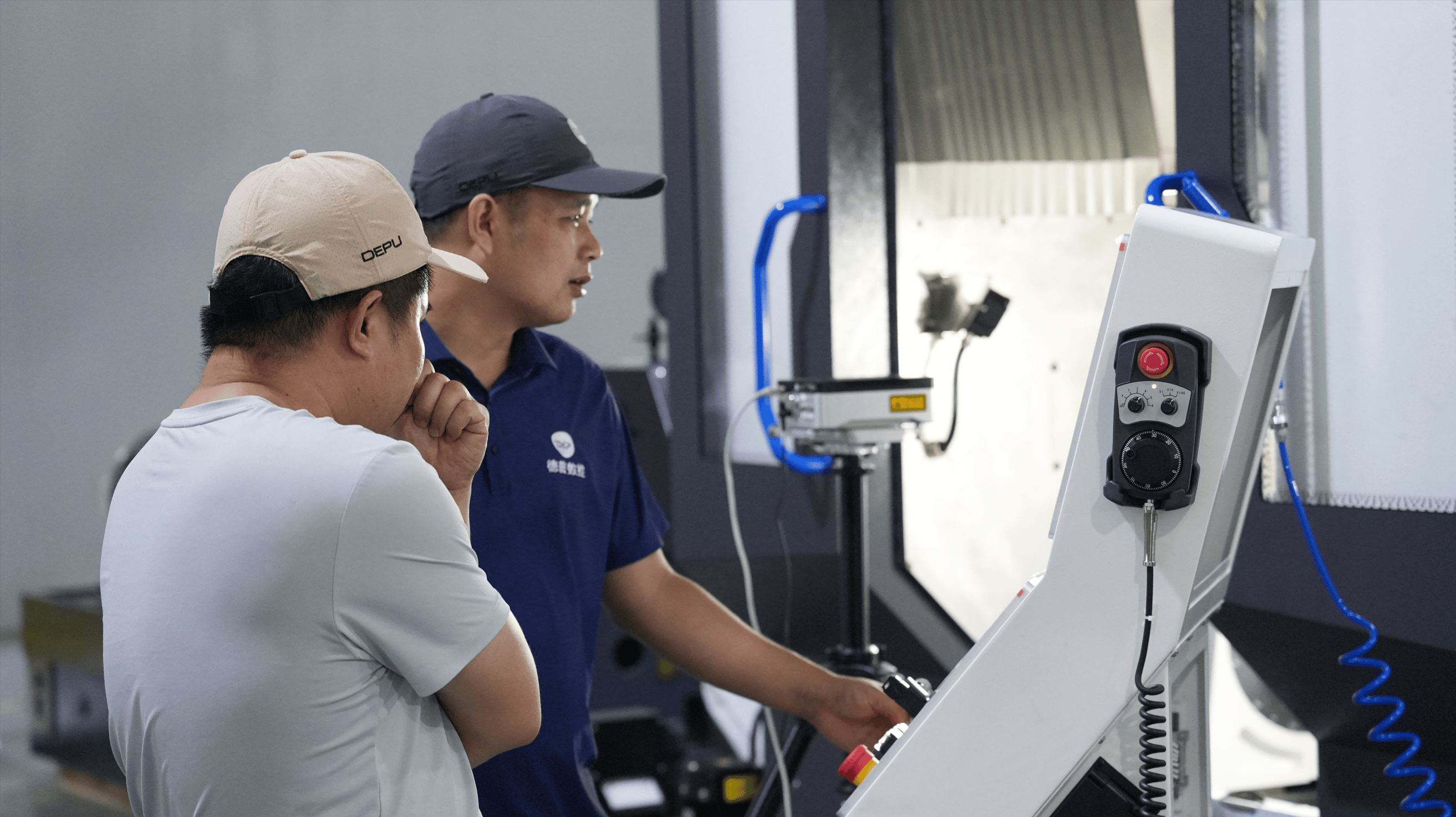
Understanding 5 Axis CNC Machine Kinematics Before You Program
The Role of Rotational Axes in 5 Axis CNC Motion
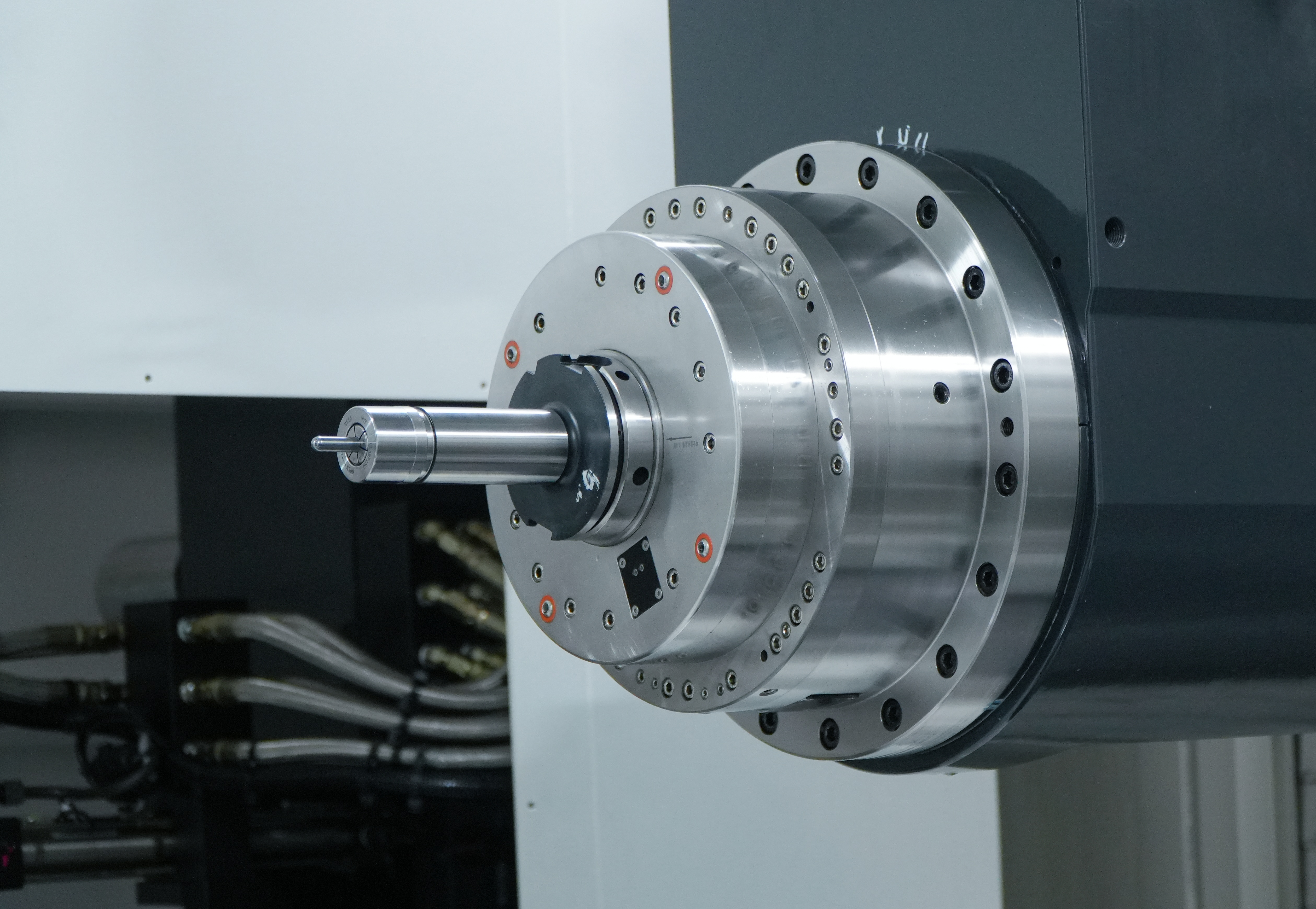
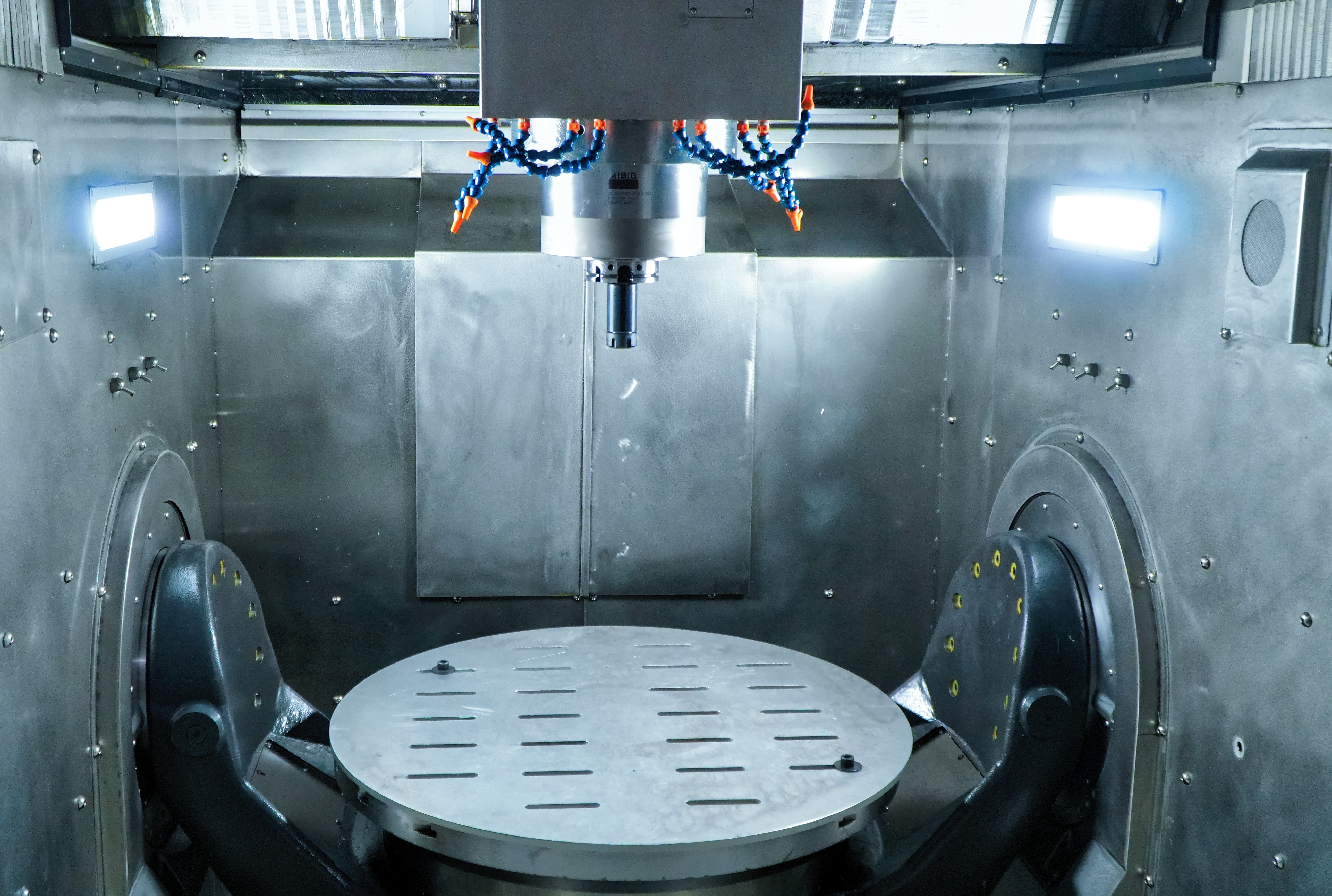
Before writing a single line of code or generating a toolpath, you need a solid understanding of how your specific 5 axis cnc machine moves. The two additional rotational axes define the machine's kinematic configuration, and this configuration directly affects how your CAM software calculates toolpaths and how your post-processor translates them into machine-readable G-code. The most common configurations are table-table, head-head, and head-table, each with different implications for workpiece positioning and axis travel limits.
In a table-table configuration, both rotational axes tilt and rotate the workpiece while the spindle moves linearly. In a head-head configuration, the spindle itself pivots in two directions while the table remains stationary. The head-table hybrid splits the rotation between the spindle and the table. Knowing which configuration your 5 axis cnc machine uses is not optional — it is the foundation of every programming decision that follows, from tool length compensation to collision avoidance strategies.
You should also familiarize yourself with the machine's axis travel limits, rotary axis home positions, and any mechanical interference zones. These physical constraints must be reflected in your CAM setup before you generate a single toolpath. Ignoring them at this stage leads to collisions, alarms, or scrapped parts during the actual cutting run.
Coordinate Systems and Work Offsets in 5 Axis CNC Programming
A 5 axis cnc machine uses multiple coordinate systems simultaneously, and understanding how they interact is critical for accurate programming. The machine coordinate system (MCS) is fixed and defined by the machine builder. The workpiece coordinate system (WCS) is defined by the programmer and tells the controller where the part origin is located relative to the machine. In 5-axis work, a third system — the tool coordinate system (TCS) — also comes into play, especially when using tilted plane machining cycles.
Work offsets on a 5 axis cnc machine must account for the rotary axis pivot points, often called the tool center point (TCP). Modern controllers use TCP control (also known as RTCP — Rotary Tool Center Point) to automatically compensate for the geometric offset between the spindle nose and the actual cutting tip as the rotary axes move. If your machine and controller support RTCP, enabling it simplifies programming significantly and reduces the risk of positional errors during simultaneous 5-axis motion.
Preparing Your CAD Model for 5 Axis CNC Machining
Geometry Cleanup and Feature Analysis
The quality of your CAD model has a direct impact on the quality of your 5 axis cnc toolpaths. Before importing your model into CAM software, perform a thorough geometry cleanup. Check for open surfaces, duplicate faces, zero-thickness walls, and any imported geometry errors that could cause the CAM system to generate incorrect or incomplete toolpaths. Most professional CAM platforms include geometry analysis tools — use them before you start programming, not after you encounter problems mid-process.
Feature analysis is equally important. Identify which surfaces require simultaneous 5-axis motion and which can be machined with 3+2 positioning — where the rotary axes index to a fixed angle and then lock while the linear axes perform the cut. Many parts that appear to require full simultaneous 5-axis motion can actually be machined more efficiently and more accurately using 3+2 strategies for the majority of their features. Reserving true simultaneous 5 axis cnc motion for only the surfaces that genuinely need it reduces programming complexity and cycle time.
Also define your stock model accurately. A precise stock definition allows the CAM system to calculate rest-machining passes correctly and avoid air-cutting, which wastes cycle time and can mask programming errors that only become visible when the tool actually engages material.
Fixturing and Workholding Considerations That Affect Programming
Workholding on a 5 axis cnc machine is fundamentally different from 3-axis setups. Because the part and table rotate during machining, the fixture must provide secure clamping while leaving the maximum amount of the part surface accessible to the cutting tool. Poorly designed fixtures force additional setups, which defeats one of the primary advantages of 5-axis machining — the ability to machine complex parts in a single setup.
When programming, you must import your fixture geometry into the CAM environment as a collision body. The CAM system will then use this geometry during toolpath verification to detect any potential collisions between the cutting tool, tool holder, spindle, and the fixture itself. Skipping this step is a common and costly mistake, particularly when machining deep pockets or undercut features where the tool holder can easily contact the workpiece or clamp during rotary axis motion.
Setting Up Your CAM Software for 5 Axis CNC Toolpaths
Selecting the Right CAM Strategy for Each Feature
CAM software is the core programming environment for any 5 axis cnc workflow. Leading platforms offer a range of 5-axis toolpath strategies, and selecting the right one for each feature is a skill that develops with experience. For open ruled surfaces and blades, swarf machining — where the side of the tool follows the surface — delivers excellent surface finish and efficient material removal. For complex freeform surfaces, flow-line machining or surface projection strategies maintain consistent tool engagement and smooth curvature following.
For prismatic features accessed from multiple angles, 3+2 indexed machining is often the most reliable and predictable strategy. The 5 axis cnc machine positions the rotary axes to the required angle, locks them, and then executes a standard 3-axis toolpath. This approach is easier to verify, produces more predictable surface finishes, and is less sensitive to machine calibration errors than full simultaneous 5-axis motion.
Regardless of the strategy chosen, always define your tool axis control carefully. Options typically include fixed axis, lead and tilt angle control, surface normal following, and collision avoidance-driven axis control. Each option produces different tool orientations and has different implications for surface quality, tool life, and machine load. Test your axis control settings in simulation before committing to a final toolpath.
Tool Selection and Cutting Parameter Setup
Tool selection for 5 axis cnc machining follows the same principles as 3-axis work — use the shortest tool that can reach the feature, maximize rigidity, and match the tool geometry to the material and operation. However, 5-axis work introduces additional considerations. Ball-nose end mills are common for freeform surface finishing because they maintain consistent contact geometry as the tool tilts. Barrel cutters and lens-shaped cutters are increasingly popular for finishing operations because their large effective radius allows wider stepovers with equivalent surface finish, dramatically reducing cycle time.
Cutting parameters — spindle speed, feed rate, depth of cut, and stepover — must be set conservatively for the first run on any new 5 axis cnc program. The dynamic nature of simultaneous 5-axis motion means that the effective chip load and cutting engagement can change rapidly as the rotary axes move. Use your CAM system's feed rate optimization features, which adjust the programmed feed rate based on material removal rate, to maintain consistent cutting conditions throughout the toolpath.
Post-Processing and G-Code Verification for 5 Axis CNC
Configuring the Correct Post-Processor
The post-processor is the software component that translates your CAM toolpaths into the specific G-code dialect understood by your 5 axis cnc machine's controller. Using the wrong post-processor — or a generic one not configured for your specific machine — is one of the most common causes of crashes and errors in 5-axis machining. Every machine builder and controller manufacturer has specific requirements for how rotary axis motion, TCP compensation, and coordinate system transformations are expressed in G-code.
Work with your machine tool supplier or CAM software vendor to obtain a post-processor that is specifically configured for your machine model and controller version. Verify that it correctly handles RTCP activation and deactivation, rotary axis direction conventions, and any machine-specific macro calls required for safe operation. A properly configured post-processor is not a luxury — it is a safety-critical component of your 5 axis cnc programming workflow.
Simulation and Collision Detection Before the First Cut
Never run a new 5 axis cnc program on the machine without first performing a full machine simulation in your CAM software or a dedicated verification tool. Machine simulation goes beyond toolpath verification — it models the complete machine envelope, including the spindle, tool holder, cutting tool, fixture, and workpiece, and checks for collisions and near-misses throughout the entire program. This step catches errors that toolpath-only verification misses, particularly collisions involving the tool holder or spindle head during rotary axis repositioning moves.
Pay particular attention to rapid traverse moves between cutting operations. These are the moves most likely to cause collisions because the machine moves at maximum speed with no cutting engagement, and the programmer's attention is typically focused on the cutting passes rather than the repositioning moves. Configure your CAM system to use safe retract heights and safe rotary axis repositioning sequences for all rapid moves in your 5 axis cnc program.
After simulation, review the G-code output directly. Look for any unexpected axis values, feed rate anomalies, or missing safety codes. Confirm that RTCP is activated at the correct points in the program and that all tool length compensation calls are correct. This manual review step takes time but consistently prevents costly mistakes on the machine.
a full machine simulation — not just a toolpath preview — before cutting any new program. On the machine, use single-block mode and reduced feed rate override for the first run of any new program.
Article Conclusion
Programming a 5 axis cnc machine requires a complete understanding of machine kinematics, CAD/CAM preparation, toolpath strategy, post-processing, simulation, and production validation. Unlike traditional 3-axis machining, 5-axis programming demands greater attention to machine configuration, rotary axis behavior, collision avoidance, and process optimization.
A successful 5 axis cnc workflow begins before the first tool movement. Engineers must correctly define machine kinematics, prepare accurate CAD geometry, select appropriate machining strategies, and verify every toolpath through simulation before cutting material. These preparation steps reduce risk, prevent costly collisions, and create a repeatable process for complex precision machining applications.
As industries such as aerospace, medical, semiconductor, automotive, and advanced manufacturing continue demanding more complex geometries and tighter tolerances, mastering 5 axis cnc programming has become a critical capability for competitive machine shops. With the right combination of skilled programming, reliable CAM software, and a capable 5 axis cnc machine, manufacturers can achieve higher accuracy, fewer setups, shorter cycle times, and expanded production capabilities.
For companies looking to improve precision machining performance and adopt advanced manufacturing solutions, investing in modern 5 axis cnc technology is not simply an equipment upgrade — it is a strategic move toward greater flexibility, efficiency, and long-term competitiveness.