
Your 5-Axis Fixture Is Working Against Your Machine
The business case for a five-axis machine is usually written in setups. Three-axis work takes three fixtures, three datums, three chances to lose a tenth. Five-axis work takes one. Multiply the saved setup hours by your shop rate and the machine pays back inside the lease — the arithmetic that gets walked through in why use 3 setups when 5-axis can do it in one.
That arithmetic is sound, and it is also the most commonly unrealised promise in a machine shop. The number of setups does not fall because a machine has two more axes. It falls because somebody engineered a fixture that lets the spindle reach every face without ever taking the part off the table. If the workholding is still designed the way it was designed for a three-axis machine, the fifth axis delivers a fraction of what it cost. Consolidating several operations onto one machine and one base is a real gain — the conditions under which one machine genuinely replaces several setups are worth reading before the tooling budget is set.
Here is the part that catches shops out: a fixture that is perfectly good on a three-axis machine can be physically unsafe on a five-axis machine, at the same part, with the same clamping force. The fixture did not change. The spindle did.
The fixture has a different job in five axes
On a three-axis machine, the fixture has one job: hold the part still, rigidly, without letting go. It can be tall. It can be wide. It can sit anywhere on the table, because the only thing that moves is the tool in a straight line toward the workpiece, and you can see that approach on the screen before you press cycle start.
On a five-axis machine the fixture has two jobs, and the second one is new. It has to hold the part, and it has to stay out of the way — at every angle the machine will pass through. That is a fundamentally different design constraint, and it is the one that gets skipped when a shop carries its existing tooling habits across to a multi-axis machine.
Put simply: on a three-axis machine the fixture competes with nothing. On a five-axis machine it competes with the spindle, the holder and the tool for the same physical space, and the outcome of that competition changes continuously during the cycle.
What the spindle is actually doing while the table turns
The failure mode is not obvious on a drawing, which is why it survives right up to the first production run.
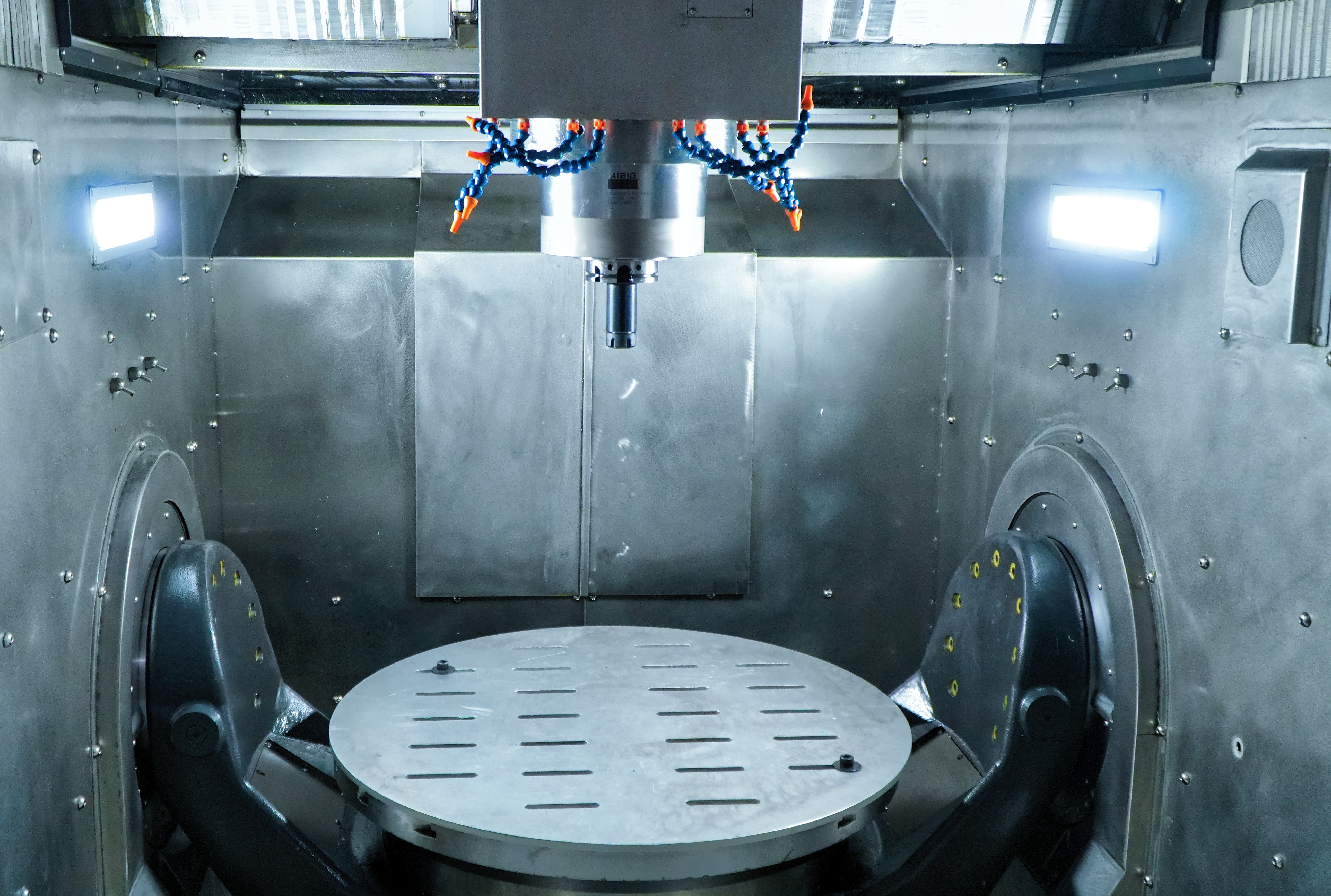
Picture the machine tilted to work an angled face. As the rotary axis swings from, say, zero degrees toward forty-five, the tool holder does not travel in a straight line. It sweeps. The holder traces an arc through the working envelope, and the diameter of that arc is set by the distance from the rotary axis's pivot point out to the holder. On a typical spindle interface with the work rotated part-way over, that swept band can be tens of millimetres wide — a band that exists nowhere in the static view of the setup, and nowhere on the fixture drawing.
Now place a clamp, a vice jaw or a riser block in that band. It may sit comfortably outside the tool diameter. It may even clear the tool holder at zero degrees. It has not cleared the swept path, and the arc is what the machine will follow at fifteen, thirty, forty-five degrees on the way through.
This is the mechanism behind a whole category of five-axis accidents that get blamed on programming. Nothing in the code is wrong. The code sent the spindle exactly where it said it would send it. The setup simply demanded that a moving object pass through a solid one.
For a machine in simultaneous five-axis work the problem is worse than for indexed work, because the path is continuous. Testing clearance at the start and end angles does not test the middle. See our comparison of 3+2 and simultaneous 5-axis machining for why the two demand different levels of verification.
Why "just raise the part" is the expensive answer
Walk into a shop that is not getting the expected output from a five-axis machine, and one of three things is usually true. This is the most common of the three, and the most expensive.
Early in the job the programmer discovers the tool cannot reach a feature with the standard low-profile clamping. The fastest fix available on a Friday afternoon is a set of parallels: raise the workpiece thirty or forty millimetres so the holder has room to come in from underneath. The feature gets cut. The setup gets signed off. Nobody records that the decision was made.
What was actually traded away is rigidity. For a simplified cantilever, deflection grows with the cube of the overhang: hold the part twice as far above its support and the setup becomes something like eight times as flexible, at the same cross-section. The symptom appears on the first heavy cut: a hum that was not there before, a surface that needs a second finishing pass, a corner that rings. The operator does the only thing available and drops the feed and the depth of cut. The program now takes longer than the three-axis version it replaced — which is exactly the outcome faster setup is supposed to prevent.
The setup savings were spent on the fixture decision, and the receipt is a longer cycle time on every part for the life of the job. There is no line on any spreadsheet where that shows up as a fixture cost.
There is a cheaper answer, and it is less exciting: choose clamping whose working height is as low as the feature access allows, and when the geometry genuinely needs high support, build the height into a dedicated low-profile plate with locating pins rather than stacking loose spacers. Riser height that is designed in can be compensated for in the process. Riser height that was improvised cannot.
The counterintuitive case: small parts on large tables
The fixture problem gets worse, not better, when the table is much bigger than the part.
A small workpiece clamped near the centre of a large rotary table, with the fixture body and jaws splayed outward toward the table edge, is a configuration that looks forgiving. It is the opposite. When the table tilts, every element that is far from the pivot travels a long way. The outer corner of the fixture climbs steeply toward the spindle housing while the part barely moves. A fixture that is fully clear when the table is flat can be inside the spindle's swept zone by the time the table reaches the angle the part actually needs.
This is one reason a large-envelope machine is not automatically a more capable answer to a small-part job. The working volume that makes the machine attractive is also the volume through which oversized workholding will swing. For more on how part geometry should drive the machine decision, see how workpiece size and weight drive machine selection.
Check the path, not the positions
The single most useful habit in five-axis fixturing is to screen the movement, not the setup.
Building the fixture, the part and the machine model into the same simulation and running the toolpath through it is not a step that can be replaced by checking a couple of snapshots at the indexed angles. If the work is 3+2, checking each discrete position is defensible. If any part of the cycle is simultaneous, the only honest check is the swept path, because that is what the machine will execute.
Do that before the fixture is manufactured, not after. Interference found in a CAD assembly costs a design revision. Interference found on the machine costs a fixture rebuild, a re-programmed part, and a week of the schedule you told the customer about.
Chip evacuation is a fixturing decision
A quieter problem, and one that shows up as an accuracy complaint rather than a crash.
Five-axis work tends to produce pockets, deep features and cuts that approach from the side. In that geometry, chips fall differently than they do on a flat three-axis job. If the fixture layout has created a pocket where swarf can collect — a recessed locating surface, a gap between the part and the plate, a clamp body with a shelf on it — the part will not seat on the same surface twice.
The result is a process that looks repeatable and is not. Dimensions hold on the first few parts, then drift, then return. Operators chase it with offsets. Inspection reports show a spread with no trend. The actual cause is that the workpiece is resting on chips about a third of the time, and stepping up the wash and air-blast routine is the fix that finally works — after weeks of looking at the wrong thing.
Two habits prevent it: give the fixture layout explicit chip paths and clearance for coolant, and never locate a part on a surface that can trap swarf.
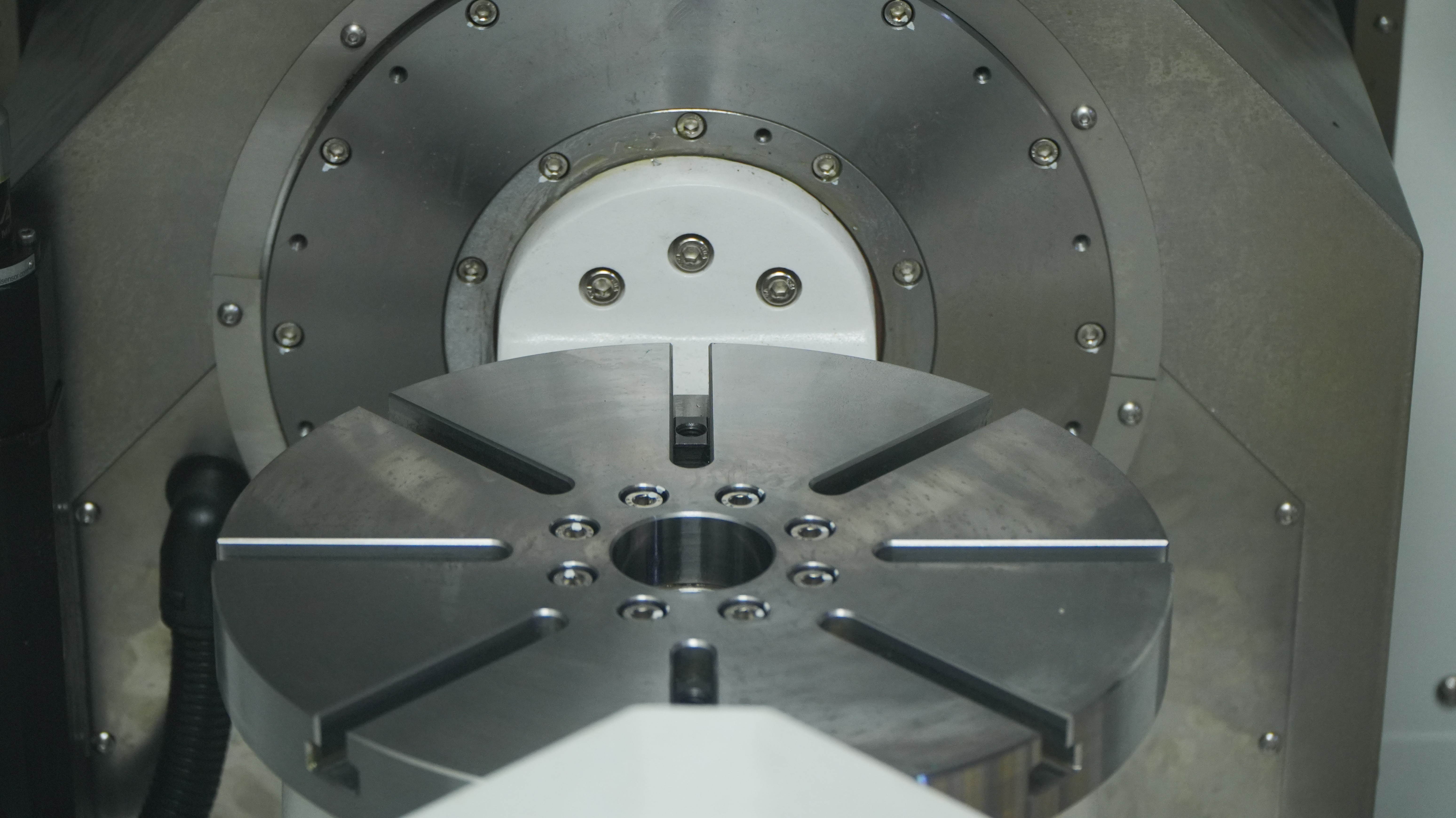
Where zero-point earns its money fastest
If you run high-mix, low-volume work, the fixture investment that pays back soonest is usually not a clever custom fixture at all. It is a standardised interface.
Consider the arithmetic. A shop changing over five or six different parts a day, with twenty minutes of dialling-in per changeover, loses roughly two hours of spindle time daily to setting up workholding, every day, forever. A zero-point system turns the fixture into a removable module: the clamping elements stay set on a pallet, the part is loaded off the machine, and the changeover becomes a locating and locking operation measured in minutes.
The same decision closes a second door. A shop that starts with a standardised base on every machine — and standardises the fixture footprint and the pull-stud pattern from the first day — can later move a fixture between machines, add a pallet pool, or introduce automated loading without rebuilding tooling. Retrofitting a base interface after the fixtures exist means re-making every fixture.
For shops doing many changes per week, the payback on a zero-point interface is usually counted in months, not years, and it is one of the few investments in the five-axis budget that gets better as the part mix gets messier.
The fixture philosophy that makes the machine pay
The strongest version of five-axis workholding is not a better fixture. It is fewer fixtures.
On a three-axis machine, each face of a complex part tends to need its own dedicated workholding — a few hundred to a few thousand in tooling per position, made obsolete the moment the drawing is revised. Five-axis machining lets one base clamping arrangement serve many faces, with the rotary axes presenting the part to the tool instead of the part being re-presented to a new fixture. That consolidation is the cost saving. It only materialises if the clamping arrangement is designed to stay out of the way rather than to hold on as hard as possible.
Practically, that means a small set of general-purpose holding elements on a standard base — a low-profile self-centring vice, a three or four-jaw chuck for round work, clamps and locating pins for irregular blanks — plus milled locating fixtures only where the geometry genuinely demands them. Not one custom fixture per part.
What to verify before the fixture is built
- The spindle and holder swept path, run through the full toolpath, with the fixture, part and stock modelled.
- Clearance at the intermediate angles, not only at the indexed positions.
- Working height above the base, and whether the stack can be lower.
- Whether any outer element of the fixture is far from the pivot centre — the further out, the further it swings.
- Chip paths and coolant flow around the locating surfaces.
- Whether the base interface is standardised, so the next fixture is cheaper than this one.
- Whether the clamping can be released and re-established without changing the part's shape.
That last item deserves a moment. A fixture that forces a thin or flexible part into shape will release it out of shape, and no amount of machine accuracy can recover it. A five-axis machine removes the excuse of re-chucking error. It does not remove the consequences of a part that was held badly.
The uncomfortable summary
Five-axis capability is sold as a machine property and delivered as a process. The machine brings the axes. The process — clamping that clears every angle the part needs, on a base that is standardised and a part that never has to be raised to be reached — is what converts the axes into fewer setups and tighter tolerances.
Most shops that are disappointed by a five-axis purchase are not short of machine. They are running a first-class machine with a third-class fixture decision that nobody flagged, because on a three-axis machine that same decision would have been fine.
This is the first of three pieces on the parts of a five-axis purchase that never make it onto the specification sheet. The others cover the post-processor problems that cause most first-part crashes and the question of who will actually program the machine.
If you are specifying workholding for a multi-axis machine and want a second opinion on clearance, fixturing height or the base interface, send us the part geometry and the operations you need to combine — we would rather discuss it before the fixture is cut than after.