
How to Set Up a Horizontal Mill for Maximum Metal Cutting
Setting up a horizontal mill correctly is one of the most consequential decisions a machinist or shop floor supervisor can make. Unlike vertical configurations, a horizontal mill positions its spindle parallel to the worktable, enabling heavier chip loads, more aggressive cuts, and superior surface finishes on complex metal workpieces. When the machine is dialed in properly from the start, every subsequent operation benefits — from roughing passes to final finishing runs. Getting that setup right, however, requires a systematic approach that accounts for alignment, tooling selection, workholding, and cutting parameters in a deliberate sequence.
This guide walks through the complete setup process for a horizontal mill with a focus on maximizing metal removal rates without sacrificing dimensional accuracy or tool life. Whether you are commissioning a new machine, reconfiguring an existing one for a new job, or troubleshooting inconsistent cut quality, the principles covered here apply directly. A well-executed horizontal mill setup translates into measurable gains in productivity, reduced scrap rates, and lower per-part costs — outcomes that matter deeply in competitive metalworking environments.

Understanding the Horizontal Mill Configuration
Spindle Orientation and Its Machining Advantages
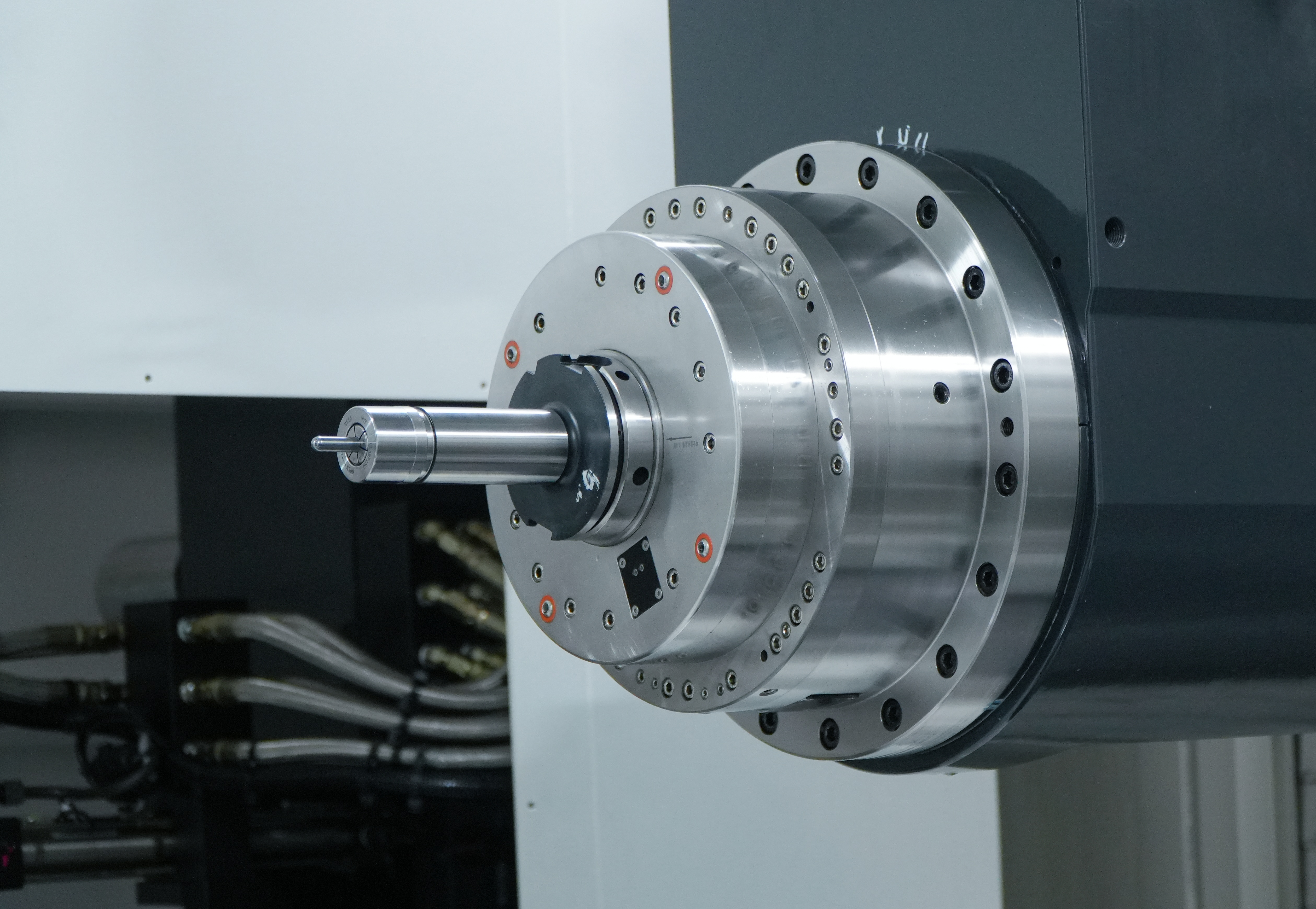
The defining characteristic of a horizontal mill is its horizontally oriented spindle, which holds the arbor and cutting tool parallel to the machine table surface. This geometry creates a fundamentally different cutting dynamic compared to vertical machines. The cutting forces generated during a horizontal mill operation are directed downward and into the table rather than laterally, which means the workpiece experiences more stable clamping loads during heavy cuts.
This orientation also allows the use of shell mills, side-and-face cutters, and straddle milling setups that are impractical or impossible on vertical configurations. For metal removal in steel, cast iron, and aluminum alloys, the horizontal mill delivers chip evacuation advantages because gravity assists in pulling chips away from the cutting zone. This reduces recutting, lowers heat buildup, and extends tool life significantly during prolonged production runs.
Understanding this geometry is not just academic — it directly informs how you position the workpiece, select your arbor length, and choose your cutting strategy. Every setup decision on a horizontal mill flows from this fundamental orientation, so internalizing it early prevents costly mistakes later in the process.
Key Machine Components to Inspect Before Setup
Before any setup begins on a horizontal mill, a thorough inspection of the machine's core components is essential. Start with the spindle taper — check for wear, scoring, or contamination that could affect tool runout. Even minor imperfections in the spindle bore translate directly into vibration and poor surface finish during cutting. Clean the taper with a lint-free cloth and inspect it visually and with a dial indicator.
Next, examine the arbor support, also called the overarm or outboard support. On a horizontal mill, the arbor support bears a significant portion of the cutting load, and any looseness or misalignment here will cause chatter, deflection, and premature tool wear. Tighten the overarm clamps firmly and verify that the support bearing is in good condition and properly lubricated.
The table, saddle, and knee should also be checked for backlash and smooth movement. Excessive backlash in the lead screws will make it difficult to hold tight tolerances during climb milling or when making fine adjustments. Document any issues found during this inspection phase — addressing them before the job starts is far less disruptive than discovering them mid-operation
Workholding and Workpiece Positioning on a Horizontal Mill
Selecting the Right Workholding Method
Workholding on a horizontal mill must account for the direction of cutting forces, which differ from those on a vertical machine. Because the spindle is horizontal, the primary cutting force acts in a direction that tends to push the workpiece along the table rather than pressing it down. This means your clamping strategy must resist lateral movement with equal or greater priority than vertical clamping.
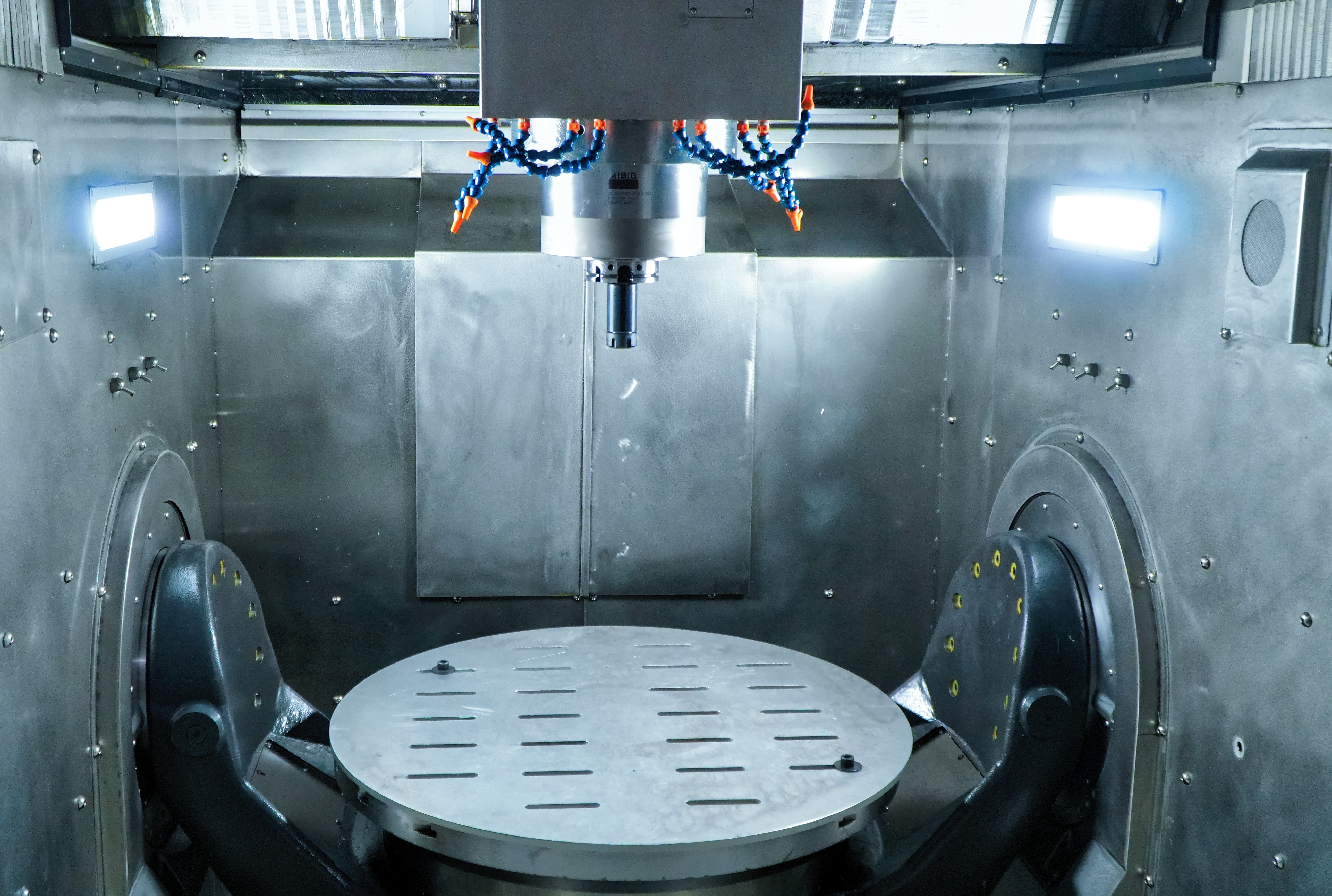
Vises are the most common workholding solution for prismatic parts on a horizontal mill. A precision machine vise bolted directly to the T-slots provides excellent rigidity for most medium-sized workpieces. For larger or irregularly shaped parts, strap clamps and step blocks offer the flexibility needed to secure the workpiece without interfering with the cutter path. Always position clamps as close to the cutting zone as practical to minimize deflection.
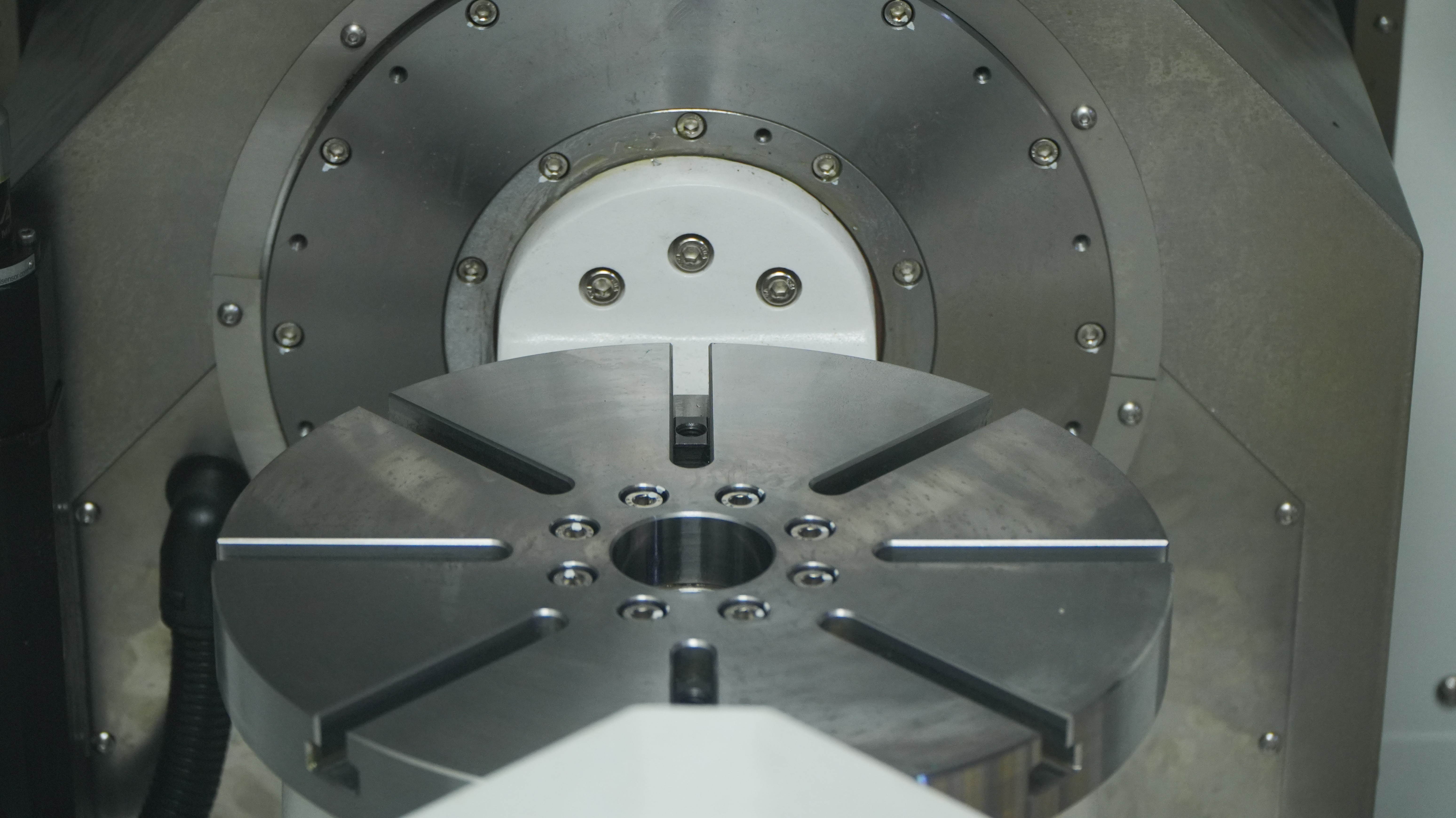
Fixture plates and tombstone fixtures are particularly valuable when running multiple parts simultaneously on a horizontal mill. The horizontal spindle orientation makes it easy to machine multiple faces of a part in a single setup by indexing the tombstone, which dramatically reduces setup time and improves positional consistency across a production batch.
Aligning the Workpiece for Accurate Metal Removal
Accurate workpiece alignment is critical on a horizontal mill because misalignment compounds across the length of a cut. Use a dial test indicator mounted in the spindle to sweep the reference surface of the workpiece before tightening the final clamp. Check both the X-axis and Y-axis alignment, and adjust the vise or fixture until the indicator reads within your required tolerance — typically within 0.001 inches for precision work.
For parts that require machining on multiple faces, establish a clear datum reference early in the setup process. Mark the datum face and use it consistently for all subsequent measurements and alignments. On a horizontal mill, losing track of your datum reference is a common source of cumulative error that can ruin an otherwise well-executed job.
Pay particular attention to the height of the workpiece relative to the arbor centerline. The cutting tool on a horizontal mill must engage the workpiece at the correct height to achieve the intended depth of cut and surface geometry. Use the knee adjustment to set this height precisely, and lock the knee firmly before beginning any cutting operation.
Arbor and Cutter Selection for Maximum Metal Cut
Choosing the Correct Arbor Length and Diameter
The arbor is the backbone of the cutting system on a horizontal mill, and selecting the right one for the job has a direct impact on rigidity and metal removal capability. As a general principle, use the shortest arbor that allows the cutter to reach the workpiece without interference. Longer arbors flex more under cutting loads, which introduces vibration, reduces accuracy, and limits the depth of cut you can take without chatter.
Arbor diameter should be matched to the cutter bore and the expected cutting forces. Larger diameter arbors are stiffer and better suited for heavy roughing operations on a horizontal mill. For finishing passes where surface quality is the priority, a slightly longer arbor may be acceptable because the cutting forces are lower and the risk of deflection is reduced.
Always ensure the arbor is clean and free of burrs before mounting. Even a small chip or burr between the arbor and the cutter bore will cause runout that degrades cut quality. Use the correct spacers and collars to position the cutter at the desired location along the arbor, and torque the arbor nut to the manufacturer's specification.
Matching Cutter Geometry to the Metal Being Cut
Cutter selection on a horizontal mill should be driven by the material being machined, the type of cut required, and the surface finish specification. For steel and cast iron, a side-and-face milling cutter with a moderate number of teeth and a positive rake angle provides a good balance of metal removal rate and tool life. For aluminum alloys, a cutter with fewer, sharper teeth and a high positive rake angle reduces built-up edge and produces a cleaner finish.
Straddle milling — using two cutters simultaneously on a horizontal mill to machine two parallel surfaces in a single pass — is one of the most productive operations available on this machine type. When setting up a straddle milling operation, ensure both cutters are the same diameter and that the spacers between them are precisely sized to achieve the required width between the machined surfaces.
Gang milling, where multiple cutters of different profiles are mounted on the same arbor, is another powerful capability of the horizontal mill. This approach allows complex cross-sectional profiles to be generated in a single pass, which is particularly valuable in high-volume production environments where cycle time reduction is a priority.
Cutting Parameters and Feed Strategy for Optimal Performance
Setting Spindle Speed and Feed Rate
Cutting speed on a horizontal mill is determined by the cutter diameter, the material being machined, and the cutter material. Use the recommended surface footage for the cutter and workpiece material combination to calculate the correct spindle RPM. Running too fast generates excessive heat and accelerates tool wear; running too slow reduces productivity and can cause rubbing rather than cutting, which also damages the tool.
Feed rate on a horizontal mill is expressed as table feed in inches or millimeters per minute, and it is calculated from the chip load per tooth, the number of teeth on the cutter, and the spindle RPM. For maximum metal removal, push the feed rate to the upper end of the recommended range for the cutter and material, then monitor the cut for signs of chatter or excessive tool deflection. Back off the feed rate incrementally if either symptom appears.
Depth of cut is where the horizontal mill truly demonstrates its advantage over vertical configurations. The rigid spindle orientation and the support provided by the overarm allow a horizontal mill to take deeper cuts with less vibration. For roughing operations in steel, depths of cut in the range of 0.100 to 0.250 inches are achievable with the right cutter and workholding setup, delivering metal removal rates that are difficult to match on a vertical machine.
Conventional vs. Climb Milling on a Horizontal Mill
The choice between conventional milling and climb milling on a horizontal mill affects surface finish, tool life, and workholding requirements. In conventional milling, the cutter rotates against the direction of table feed, which means the chip starts thin and grows thicker as the tooth completes its arc. This approach is more forgiving of backlash in the table lead screws and is generally preferred for roughing operations on older machines.
Climb milling, where the cutter rotates in the same direction as the table feed, produces a thicker chip at the start of the cut that thins as the tooth exits. This results in lower cutting temperatures, better surface finish, and longer tool life. However, climb milling on a horizontal mill requires a machine with minimal backlash and a rigid workholding setup, because the cutting forces tend to pull the workpiece into the cutter rather than pushing it away.
For finishing passes on a horizontal mill, climb milling is almost always the preferred choice when the machine and setup can support it. The improved surface finish and reduced heat generation justify the additional attention to workholding rigidity and backlash control that climb milling demands.
Verification, Trial Cuts, and Final Adjustments
Running a Trial Cut to Validate the Setup
Before committing to a full production run, always perform a trial cut on a horizontal mill setup to verify that all parameters are correct. Take a light finishing pass across the workpiece and measure the result with a micrometer or vernier caliper. Check the dimension against the drawing tolerance, inspect the surface finish visually and with a profilometer if required, and listen for any unusual sounds that might indicate chatter or tool rubbing.
If the trial cut reveals dimensional error, trace it back systematically. Check the workpiece alignment first, then the arbor runout, then the depth-of-cut setting. On a horizontal mill, most dimensional errors in the trial cut can be attributed to one of these three sources. Correct the root cause rather than compensating with an offset, which only masks the underlying problem.
Surface finish problems on a horizontal mill trial cut are usually caused by incorrect spindle speed, excessive feed rate, or arbor deflection. Adjust one variable at a time and re-cut until the finish meets specification. Document the final cutting parameters so they can be reproduced consistently across the production run.
Maintaining Setup Integrity During Production
Once the horizontal mill setup is validated, maintaining its integrity throughout the production run requires periodic checks. Re-inspect the workholding clamps after the first few parts to ensure they have not loosened due to vibration. Check the arbor nut torque at the start of each shift, and monitor the cutter for signs of wear — dull teeth on a horizontal mill cutter cause increased cutting forces that can shift the workpiece or cause dimensional drift.
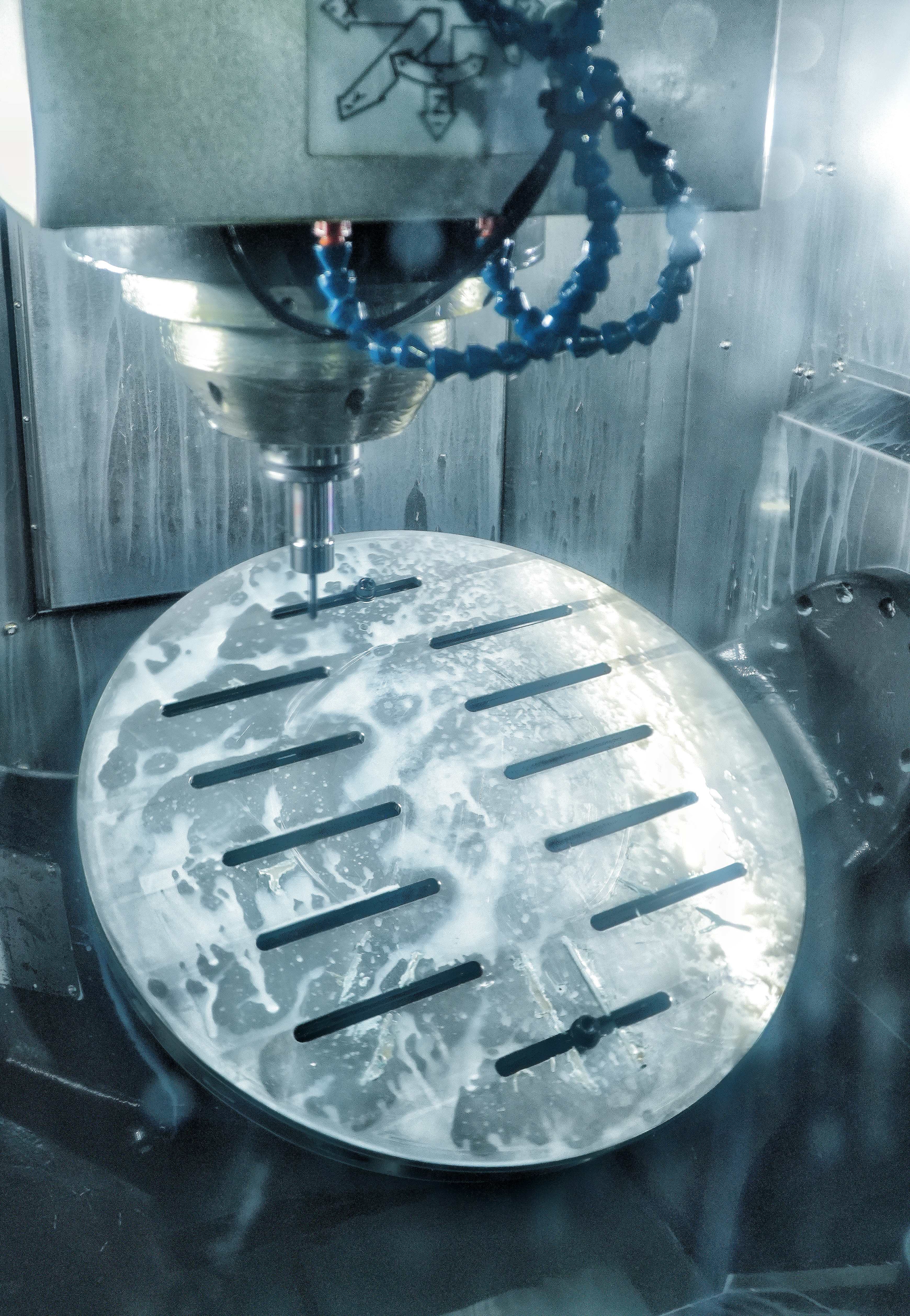
Coolant application is another factor that affects setup integrity on a horizontal mill. Flood coolant directed at the cutting zone helps control temperature, flushes chips away from the cutter, and extends tool life. Ensure the coolant nozzles are positioned to deliver fluid directly to the cutter-workpiece interface, and check the coolant concentration regularly to maintain its effectiveness.
Keep a setup sheet for each job that records the workholding method, arbor configuration, cutter specifications, cutting parameters, and any adjustments made during the trial cut phase. This documentation makes it possible to reproduce the horizontal mill setup quickly and accurately the next time the same job is run, which is a significant time and cost saving in a production environment.
FAQ
What is the main advantage of using a horizontal mill over a vertical mill for heavy metal cutting?
A horizontal mill offers superior rigidity during heavy cuts because the spindle orientation directs cutting forces downward into the table, reducing vibration and deflection. This allows deeper cuts, higher feed rates, and better chip evacuation compared to vertical configurations, making it the preferred choice for high-volume metal removal in steel, cast iron, and other tough alloys.
How do I reduce chatter on a horizontal mill during aggressive cuts?
Chatter on a horizontal mill is most commonly caused by arbor deflection, loose workholding, or incorrect cutting parameters. Start by shortening the arbor to the minimum length needed, tighten all workholding clamps, and verify the overarm support bearing is in good condition. If chatter persists, reduce the depth of cut or feed rate incrementally until the vibration disappears, then investigate whether the cutter has worn teeth that need replacement.
Can a horizontal mill perform the same operations as a vertical mill?
A horizontal mill can perform most of the same fundamental milling operations as a vertical machine, including face milling, slotting, and profile milling, but it excels at operations that leverage its horizontal spindle — such as straddle milling, gang milling, and side-and-face milling. Some operations that require a vertical spindle orientation, such as drilling straight down into a flat surface, are more naturally suited to a vertical mill or a machining center with a vertical spindle option.
How often should I inspect the arbor and overarm support on a horizontal mill?
The arbor and overarm support on a horizontal mill should be inspected at the start of every new job setup and at the beginning of each production shift during long runs. Check the arbor for runout with a dial indicator, inspect the overarm support bearing for play or roughness, and verify that all locking mechanisms are fully engaged. Regular inspection prevents the gradual degradation of setup integrity that leads to dimensional drift and poor surface finish over time.